SNIS220B March 2020 – November 2020 TMP64-Q1
PRODUCTION DATA
- 1 Features
- 2 Applications
- 3 Description
- 4 Revision History
- 5 Device Comparison Table
- 6 Pin Configuration and Functions
- 7 Specifications
- 8 Detailed Description
- 9 Application and Implementation
- 10Power Supply Recommendations
- 11Layout
- 12Device and Documentation Support
- 13Mechanical, Packaging, and Orderable Information
Package Options
Mechanical Data (Package|Pins)
Thermal pad, mechanical data (Package|Pins)
Orderable Information
9.2.1.2.2 Thermal Foldback
One application that uses the output voltage of the TMP64-Q1 in an active control circuit is thermal foldback. This is performed to reduce, or fold back, the current driving a string of LEDs, for example. At high temperatures, the LEDs begin to heat up due to environmental conditions and self heating. Thus, at a certain temperature threshold based on the LED's safe operating area, the driving current must be reduced to cool down the LEDs and prevent thermal runaway. The TMP64-Q1 voltage output increases with temperature when the output is in the lower position of the voltage divider and can provide a response used to fold back the current. Typically, the current is held at a specified level until a high temperature is reached, known as the knee point, where the current must be rapidly reduced. To better control the temperature/voltage sensitivity of the TMP64-Q1, a rail-to-rail operational amplifier is used. In the example shown in Figure 9-6, the temperature “knee” where the foldback begins is set by the reference voltage (2.5 V) at the positive input, and the feedback resistors set the response of the foldback curve. The foldback knee point may be chosen based on the output of the voltage divider and the corresponding temperature from Equation 5 (like 110 °C, for example). A buffer is used in-between the voltage divider with RTMP64-Q1 and the input to the op amp to prevent loading and variations in VTEMP.
 Figure 9-6 Thermal Foldback Using TMP64-Q1 Voltage Divider and a Rail-to-Rail Op Amp
The op amp remains high as long as the voltage output is below VRef. When the temperature goes above 110 °C, then the output swings low to the 0-V rail of the op amp. The rate at which the foldback occurs is dependent on the feedback network, RFB and R1, which varies the gain of the op amp, G, given by Equation 6. This in return controls the voltage/temperature sensitivity of the circuit. This voltage output is fed into a LED driver IC that adjusts output current accordingly. The final output voltage used for thermal foldback is VOUT, and is given in Equation 7. In this example where the knee point is set at 110 °C, the output voltage curve is as shown in Figure 9-7.
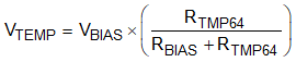

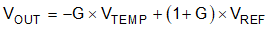
 Figure 9-7 Thermal Foldback Voltage Output Curve