SLASEP7A May 2020 – May 2022 TMUXHS4212
PRODUCTION DATA
- 1 Features
- 2 Applications
- 3 Description
- 4 Revision History
- 5 Pin Configuration and Functions
- 6 Specifications
- 7 Parameter Measurement Information
- 8 Detailed Description
- 9 Application and Implementation
- 10Power Supply Recommendations
- 11Layout
- 12Device and Documentation Support
- 13Mechanical, Packaging, and Orderable Information
Package Options
Mechanical Data (Package|Pins)
- RKS|20
Thermal pad, mechanical data (Package|Pins)
- RKS|20
Orderable Information
9.2.1 USB 3.2 Implementation for USB Type-C
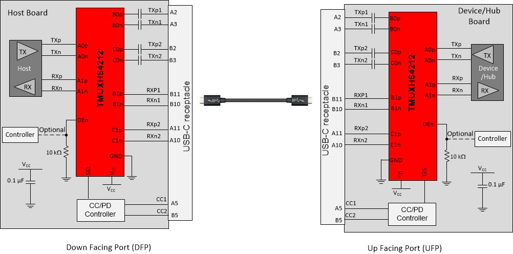
The TMUXHS4212 can be used in USB Type-C implementation to mux USB 3.2 superspeed signals (TX1 and RX1 pairs versus TX2 and RX2 pairs) to accommodate plug flips. In typical use cases, the mux selection is done by a USB Type-C Channel Configuration (CC) or Power Delivery (PD) controller. The device can used on a USB Type-C DFP, UFP, or DRP port. Figure 9-2 shows two USB Type-C connector applications with both a host and device side. The cable between the two connectors swivels the pairs to properly route the signals to the correct pin. The other applications are more generic because different connectors can be used.
 Figure 9-2 USB 3.2 Implementation for USB Type-C
Connector