SLIS032B July 1995 – June 2015 TPIC6B595
PRODUCTION DATA.
- 1 Features
- 2 Applications
- 3 Description
- 4 Revision History
- 5 Pin Configuration and Functions
- 6 Specifications
- 7 Parameter Measurement Information
- 8 Detailed Description
- 9 Application and Implementation
- 10Power Supply Recommendations
- 11Layout
- 12Device and Documentation Support
- 13Mechanical, Packaging, and Orderable Information
Package Options
Mechanical Data (Package|Pins)
Thermal pad, mechanical data (Package|Pins)
Orderable Information
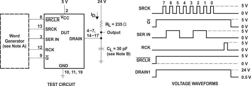
7 Parameter Measurement Information

A. The word generator has the following characteristics: tr ≤ 10 ns, tf ≤ 10 ns, tw = 300 ns, pulsed repetition rate
(PRR) = 5 kHz, ZO = 50 Ω.
(PRR) = 5 kHz, ZO = 50 Ω.
B. CL includes probe and jig capacitance.
Figure 8. Resistive-Load Test Circuit and Voltage Waveforms

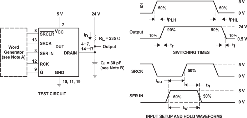
A. The word generator has the following characteristics: tr ≤ 10 ns, tf ≤ 10 ns, tw = 300 ns, pulsed repetition rate
(PRR) = 5 kHz, ZO = 50 Ω.
(PRR) = 5 kHz, ZO = 50 Ω.
B. CL includes probe and jig capacitance.
Figure 9. Test Circuit, Switching Times, and Voltage Waveforms

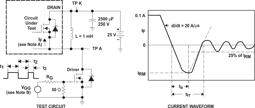
A. The DRAIN terminal under test is connected to the TP K test point. All other terminals are connected together and connected to the TP A test point.
B. The VGG amplitude and RG are adjusted for di/dt = 20 A/µs. A VGG double-pulse train is used to set IF = 0.1 A, where t1 = 10 µs, t2 = 7 µs, and t3 = 3 µs.
Figure 10. Reverse-Recovery-Current Test Circuit and Waveforms of Source-to-Drain Diode

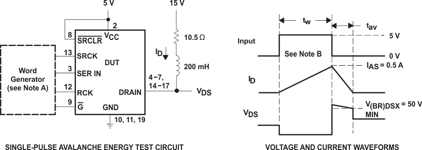
A. The word generator has the following characteristics: tr ≤ 10 ns, tf ≤10 ns, ZO = 50 Ω.
B. Input pulse duration, tw, is increased until peak current IAS = 0.5 mA.
Energy test level is defined as EAS = IAS × V(BR)DSX × tav/2 = 30 mJ.
Figure 11. Single-Pulse Avalanche Energy Test Circuit and Waveforms
Energy test level is defined as EAS = IAS × V(BR)DSX × tav/2 = 30 mJ.