SNAS679 September 2016 TPL5010-Q1
PRODUCTION DATA.
- 1 Features
- 2 Applications
- 3 Description
- 4 Revision History
- 5 Device Comparison Table
- 6 Pin Configuration and Functions
- 7 Specifications
- 8 Detailed Description
- 9 Application and Implementation
- 10Power Supply Recommendations
- 11Layout
- 12Device and Documentation Support
- 13Mechanical, Packaging, and Orderable Information
Package Options
Mechanical Data (Package|Pins)
- DDC|6
Thermal pad, mechanical data (Package|Pins)
Orderable Information
9 Application and Implementation
NOTE
Information in the following applications sections is not part of the TI component specification, and TI does not warrant its accuracy or completeness. TI’s customers are responsible for determining suitability of components for their purposes. Customers should validate and test their design implementation to confirm system functionality.
9.1 Application Information
In battery-powered applications, one design constraint is the need for low current consumption. The TPL5010-Q1 is ideal for applications where there is a need to monitor environmental conditions at a fixed time interval. Often in these applications, a watchdog or other internal timer in a µC is used to implement a wakeup function. Using the TPL5010-Q1 to implement the watchdog function will consume only tens of nA, significantly improving the power consumption of the system.
9.2 Typical Application
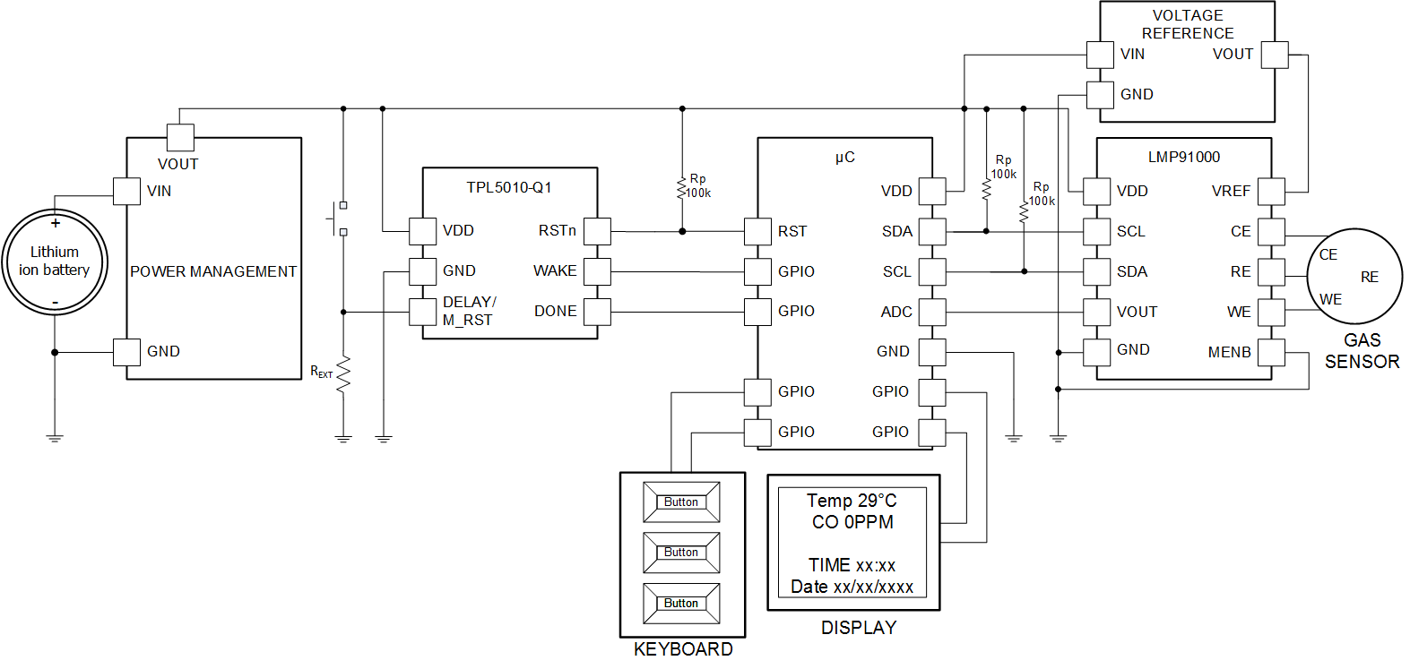
The TPL5010-Q1 can be used in conjunction with environment sensors to build a low-power environment data-logger, such as an air quality data-logger. In this application, due to the monitored phenomena, the µC and the front end of the sensor spend most of the time in the idle state, waiting for the next logging interval, usually a few hundred of milliseconds. Figure 13 illustrates a data logging application based on a µC, and a front end for a gas sensor based on the LMP91000.
 Figure 13. Data-Logger
9.2.1 Design Requirements
The design is driven by the low current consumption constraint. The data are usually acquired on a rate that ranges between 1 s and 10 s. The highest necessity is the maximization of the battery life. The TPL5010-Q1 helps achieve that goal because it allows putting the µC in its lowest power mode. The TPL5010-Q1 will take care of the watchdog and the timing.
9.2.2 Detailed Design Procedure
When the main constraint is the battery life, the selection of a low-power voltage reference, µC, and display is mandatory. The first step in the design is the calculation of the power consumption of the devices in their different mode of operations. For instance, the LMP91000 burns most of the power when in gas measurement mode, then according to the connected gas sensor it has 2 idle states: stand-by and deep sleep. The same is true for the µC, such as one of the MSP430 family, which can be placed in one of its lower power modes, such as LMP3.5 or LMP4.5. In this case, the TPL5010-Q1 can be used to implement the watchdog and wakeup timing functions.
After the power budget calculation it is possible to select the appropriate time interval which satisfies the application constraints and maximize the life of the battery.
9.2.3 Application Curves
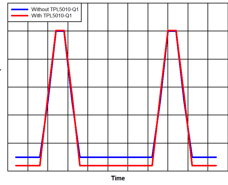
 Figure 14. Effect of TPL5010-Q1 on Current Consumption