SLVSER7 October 2020 TPS23731
PRODUCTION DATA
- 1 Features
- 2 Applications
- 3 Description
- 4 Revision History
- 5 Device Comparison Table
- 6 Pin Configuration and Functions
- 7 Specifications
-
8 Detailed Description
- 8.1 Overview
- 8.2 Functional Block Diagram
- 8.3
Feature Description
- 8.3.1 CLS Classification
- 8.3.2 DEN Detection and Enable
- 8.3.3 APD Auxiliary Power Detect
- 8.3.4 Internal Pass MOSFET
- 8.3.5 T2P and APDO Indicators
- 8.3.6
DC-DC Controller Features
- 8.3.6.1 VCC, VB, VBG and Advanced PWM Startup
- 27
- 8.3.6.2 CS, Current Slope Compensation and blanking
- 8.3.6.3 COMP, FB, EA_DIS, CP, PSRS and Opto-less Feedback
- 8.3.6.4 FRS Frequency Setting and Synchronization
- 8.3.6.5 DTHR and Frequency Dithering for Spread Spectrum Applications
- 8.3.6.6 SST and Soft-Start of the Switcher
- 8.3.6.7 SST, I_STP, LINEUV and Soft-Stop of the Switcher
- 8.3.7 Switching FET Driver - GATE
- 8.3.8 EMPS and Automatic MPS
- 8.3.9 VDD Supply Voltage
- 8.3.10 RTN, AGND, GND
- 8.3.11 VSS
- 8.3.12 Exposed Thermal pads - PAD_G and PAD_S
- 8.4
Device Functional Modes
- 8.4.1 PoE Overview
- 8.4.2 Threshold Voltages
- 8.4.3 PoE Start-Up Sequence
- 8.4.4 Detection
- 8.4.5 Hardware Classification
- 8.4.6 Maintain Power Signature (MPS)
- 8.4.7 Advanced Start-Up and Converter Operation
- 8.4.8 Line Undervoltage Protection and Converter Operation
- 8.4.9 PD Self-Protection
- 8.4.10 Thermal Shutdown - DC-DC Controller
- 8.4.11 Adapter ORing
-
9 Application and Implementation
- 9.1 Application Information
- 9.2
Typical Application
- 9.2.1
Design Requirements
- 9.2.1.1
Detailed Design Procedure
- 9.2.1.1.1 Input Bridges and Schottky Diodes
- 9.2.1.1.2 Input TVS Protection
- 9.2.1.1.3 Input Bypass Capacitor
- 9.2.1.1.4 Detection Resistor, RDEN
- 9.2.1.1.5 Classification Resistor, RCLS.
- 9.2.1.1.6 APD Pin Divider Network, RAPD1, RAPD2
- 9.2.1.1.7 Setting Frequency (RFRS) and Synchronization
- 9.2.1.1.8 Bias Supply Requirements and CVCC
- 9.2.1.1.9 APDO, T2P Interface
- 9.2.1.1.10 Output Voltage Feedback Divider, RAUX, R1,R2
- 9.2.1.1.11 Frequency Dithering for Conducted Emissions Control
- 9.2.1.1
Detailed Design Procedure
- 9.2.1
Design Requirements
- 10Power Supply Recommendations
- 11Layout
- 12Device and Documentation Support
- 13Mechanical, Packaging, and Orderable Information
Package Options
Mechanical Data (Package|Pins)
- RMT|45
Thermal pad, mechanical data (Package|Pins)
Orderable Information
3 Description
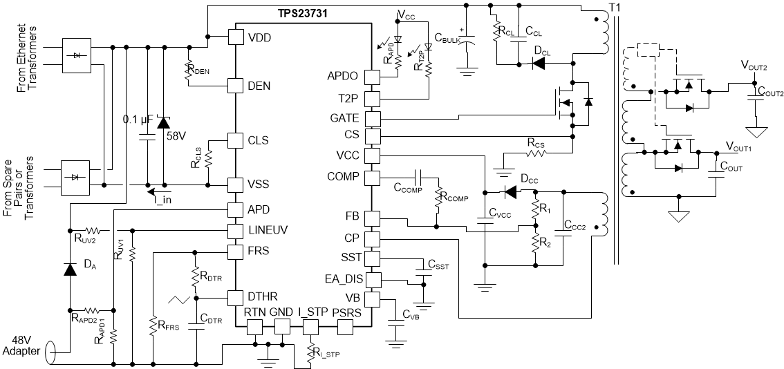
The TPS23731 device combines a Power over Ethernet (PoE) powered device (PD) interface, and a current-mode DC-DC controller optimized for flyback switching regulator designs where the use of primary-side regulation (PSR) is supported. The PoE interface supports the IEEE 802.3bt and IEEE 802.3at standards for applications needing up to 25.5 W or less at PD input.
Programmable spread spectrum frequency dithering (SSFD) is provided to minimize the size and cost of EMI filter. Advanced Startup with adjustable soft-start helps to use minimal bias capacitor while simplifying converter startup and hiccup design, also ensuring that IEEE 802.3bt/at startup requirements are met.
The soft-stop feature minimizes stress on switching sync FET(s), allowing FET BOM cost reduction.
The PSR feature of the DC-DC controller uses feedback from an auxiliary winding for control of the output voltage, eliminating the need for external shunt regulator and optocoupler. It is optimized for continuous conduction mode (CCM), and can work with secondary side synchronous rectification, resulting in optimum efficiency, regulation accuracy and step load response over multiple outputs.
The DC-DC controller features slope compensation and blanking. Typical switching frequency is 250 kHz.
The automatic MPS enables applications with low power modes or multiple power feeds. It automatically adjusts its pulsed current amplitude and duration according to PSE Type and system conditions, to maintain power while minimizing consumption.
| PART NUMBER | PACKAGE | BODY SIZE (NOM) |
|---|---|---|
| TPS23731 | VSON (45) | 7.00 mm × 5.00 mm |
 Simplified Application