SLVSAJ4C September 2010 – October 2017
PRODUCTION DATA.
- 1Features
- 2Applications
- 3Description
- 4Revision History
- 5Pin Configuration and Functions
- 6Specifications
- 7Detailed Description
- 8Device and Documentation Support
- 9Mechanical, Packaging, and Orderable Information
Package Options
Mechanical Data (Package|Pins)
- DBV|5
Thermal pad, mechanical data (Package|Pins)
Orderable Information
7 Detailed Description
7.1 Overview
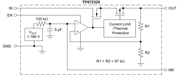
The TPS723xx-Q1 is a low-dropout negative linear voltage regulator with a rated current of 200 mA. It features very low noise and high power-supply rejection ratio (PSRR), making it ideal for high-sensitivity analog and RF applications. A shutdown mode is available, reducing ground current to 2 μA maximum over temperature and process. The TPS723xx-Q1 comes in a small SOT23 package, specified over a –40°C to 125°C junction-temperature range.
7.2 Functional Block Diagram

7.3 Feature Description
7.3.1 Enable
The enable pin is active above 1.5 V and below –1.5 V, allowing control by a standard TTL signal or by connection to VI if not used. Driving the pin to GND turns off most internal circuitry, putting the TPS723xx-Q1 into shutdown mode, drawing 2-μA maximum ground current.
7.3.2 Capacitor Selection for Stability
Use appropriate input and output capacitors for the intended application. The TPS723xx-Q1 only requires the use of a 2.2-μF ceramic output capacitor for stable operation. Both the capacitor value and ESR affect stability, output noise, PSRR, and transient response. For typical applications, a 2.2-μF ceramic output capacitor located close to the regulator is sufficient.
7.3.3 Output Noise
Without external bypassing, output noise of the TPS723xx-Q1 from 10 Hz to 100 kHz is 200 μVRMS typical. The dominant contributor to output noise is the internal band-gap reference. Adding an external 0.01-μF capacitor to ground reduces the noise to 60 μVRMS. To achieve best noise performance, use appropriate low-ESR capacitors for bypassing noise at the NR and OUT pins. See Figure 18 in the Typical Characteristics section.
7.3.4 Power-Supply Rejection
The TPS723xx-Q1 offers a very high PSRR for applications with noisy input sources or highly sensitive output supply lines. For best PSRR, use high-quality input and output capacitors.
7.3.5 Current Limit
The TPS723xx-Q1 has internal circuitry that monitors and limits output current to protect the regulator from damage under all load conditions. When output current reaches the output-current limit (550 mA typical), protection circuitry turns on, reducing output voltage to ensure that current does not increase. See Figure 8 in the Typical Characteristics section.
Do not drive the output more than 0.3 V above the input. Doing so biases the body diode in the pass FET, allowing current to flow from the output to the input. The device does not limit this current. If this condition is likely, take care to limit the reverse current externally.
7.3.6 Thermal Protection
As protection from damage due to excessive junction temperatures, the TPS723xx-Q1 has internal protection circuitry. When junction temperature reaches approximately 165°C, the output device turns off. After the device has cooled by about 20°C, the output device turns on, allowing normal operation. For reliable operation, design is for worst-case junction temperature of ≤ 125°C, taking into account worst-case ambient temperature and load conditions.
7.3.7 Adjustable Voltage Applications
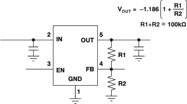
The TPS72301-Q1 allows designers to specify any output voltage from –10 V to –1.2 V. As shown in the application circuit in Figure 24, use of an external resistor divider scales the output voltage (VOUT) to the reference voltage. For best accuracy, use precision resistors for R1 and R2. Use the equations in Figure 24 to determine the values for the resistor divider.
 Figure 24. TPS72301-Q1 Adjustable LDO Regulator Programming