SLVSD64 December 2015 TPS7A6650H-Q1
PRODUCTION DATA.
- 1 Features
- 2 Applications
- 3 Description
- 4 Revision History
- 5 Pin Configuration and Functions
- 6 Specifications
- 7 Detailed Description
- 8 Application and Implementation
- 9 Power Supply Recommendations
- 10Layout
- 11Device and Documentation Support
- 12Mechanical, Packaging, and Orderable Information
Package Options
Mechanical Data (Package|Pins)
- DGN|8
Thermal pad, mechanical data (Package|Pins)
- DGN|8
Orderable Information
8 Application and Implementation
NOTE
Information in the following applications sections is not part of the TI component specification, and TI does not warrant its accuracy or completeness. TI’s customers are responsible for determining suitability of components for their purposes. Customers should validate and test their design implementation to confirm system functionality.
8.1 Application Information
The TPS7A6650H-Q1 device is a 150-mA low-dropout linear regulator designed for up to 40-V Vin operation with only 12-µA quiescent current at no load.
8.2 Typical Application
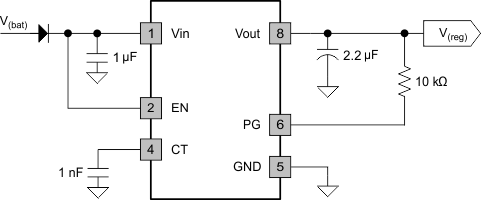
Figure 16 shows a typical application circuits for the TPS7A6650H-Q1. One may use different values of external components, depending on the end application. An application may require a larger output capacitor during fast load steps in order to prevent reset from occurring. TI recommends a low-ESR ceramic capacitor with dielectric of type X7R or X8R.
8.2.1 TPS7A6650H-Q1 Typical Application
 Figure 16. Typical Application Schematic for TPS7A6650H-Q1
8.2.1.1 Design Requirements
For this design example, use the parameters listed in Table 1 as the design parameters.
Table 1. Design Parameters
| DESIGN PARAMETER | EXAMPLE VALUE |
|---|---|
| Input voltage range | 4 V to 40 V |
| Output voltage | 5 V |
| Output current rating | 50 mA |
| Output capacitor range | 2.2 µF to 100 µF |
| Output capacitor ESR range | 1 mΩ to 2 Ω |
| CT capacitor range | 100 pF to 100 nF |
8.2.1.2 Detailed Design Procedure
To begin the design process, determine the following:
- Input voltage range
- Output voltage
- Output current rating
- Input capacitor
- Output capacitor
- Power-up-reset delay time
8.2.1.2.1 Input Capacitor
The device requires an input decoupling capacitor, the value of which depends on the application. The typical recommended value for the decoupling capacitor is 10 µF. The voltage rating must be greater than the maximum input voltage.
8.2.1.2.2 Output Capacitor
The device requires an output capacitor to stablize the output voltage. The capacitor value should be between 2.2 µF and 100 µF. The ESR range should be between 1 mΩ and 2 Ω. TI recommends to selecting a ceramic capacitor with low ESR to improve the load transient response.
8.2.1.3 Application Performance Plot
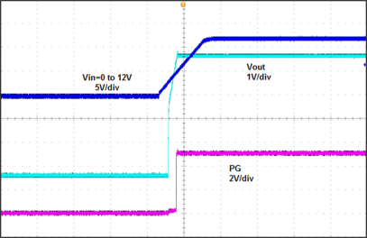
 Figure 17. Power Up (5 V), 20 ms/div, IL = 20 mA