SLUS334F August 1995 – August 2022 UC1823A , UC1825A , UC2823A , UC2823B , UC2825A , UC2825B , UC3823A , UC3823B , UC3825A , UC3825B
PRODUCTION DATA
- 1Features
- 2Description
- 3Revision History
- 4Ordering Information
- 5Pin Configuration and Functions
- 6Specifications
- 7Application and Implementation
- 8Device and Documentation Support
- 9Mechanical, Packaging, and Orderable Information
Package Options
Refer to the PDF data sheet for device specific package drawings
Mechanical Data (Package|Pins)
- J|16
Thermal pad, mechanical data (Package|Pins)
Orderable Information
7.2 UVLO, SOFT-START AND FAULT MANAGEMENT
Soft-start is programmed by a capacitor on the SS pin. At power up, SS is discharged. When SS is low, the error amplifier output is also forced low. While the internal 9-μA source charges the SS pin, the error amplifier output follows until closed loop regulation takes over.
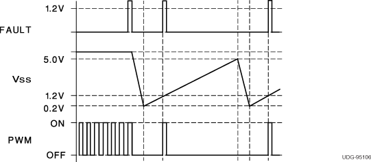
Anytime ILIM exceeds 1.2 V, the fault latch is set and the output pins are driven low. The soft-start cap is then discharged by a 250-μA current sink. No more output pulses are allowed until soft-start is fully discharged and ILIM is below 1.2 V. At this point the fault latch resets and the chip executes a soft-start.
Should the fault latch get set during soft-start, the outputs are immediately terminated, but the soft-start capacitor does not discharge until it has been fully charged first. This results in a controlled hiccup interval for continuous fault conditions.
 Figure 7-2 Soft-Start and Fault Waveforms