SLUSFC2 august 2023 UCC23113
PRODUCTION DATA
- 1
- 1 Features
- 2 Applications
- 3 Description
- 4 Revision History
- 5 Pin Configuration and Function
- 6 Specifications
- 7 Parameter Measurement Information
- 8 Detailed Description
- 9 Application and Implementation
- 10Power Supply Recommendations
- 11Layout
- 12Device and Documentation Support
- 13Mechanical, Packaging, and Orderable Information
Package Options
Mechanical Data (Package|Pins)
- DWY|6
Thermal pad, mechanical data (Package|Pins)
Orderable Information
3 Description
The UCC23113 opto-compatible, single-channel, isolated gate driver for IGBTs, MOSFETs and SiC MOSFETs, with 5-A source and 5-A sink peak output current and 1.5-kVDC functional isolation. The high supply voltage range of 30 V allows the use of bipolar supplies to effectively drive IGBTs and SiC power FETs. The UCC23113 can drive both low-side and high-side power FETs.
Key features and characteristics bring significant performance and reliability upgrades over standard opto-coupler based gate drivers while maintaining pin-to-pin compatibility in both schematic and layout design. Performance highlights include high common-mode transient immunity (CMTI), low propagation delay, and small pulse width distortion. Tight process control results in small part-to-part skew. The input stage is an emulated diode (e-diode) which means long term reliability and excellent aging characteristics compared to traditional LEDs found in optocoupler gate drivers. It is offered in a stretched SO6 package with >8.5-mm creepage and clearance, and a mold compound from material group I which has a comparative tracking index (CTI) > 600 V.
The high performance and reliability of the UCC23113 makes it ideal for use in all types of motor drives, solar inverters, industrial power supplies, and appliances. The higher operating temperature opens up opportunities for applications not previously able to be supported by traditional optocouplers.
| PART NUMBER | PACKAGE(1) | UVLO Level |
|---|---|---|
| UCC23113CDWYR | Stretched SO-6 | 12 V |
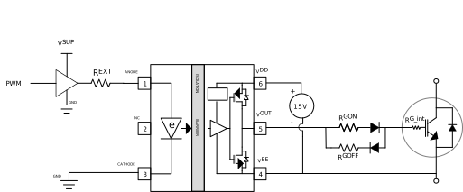 Typical Application Schematic