SBOS094B January 1998 – December 2014 DRV134 , DRV135
PRODUCTION DATA.
- 1 Features
- 2 Applications
- 3 Description
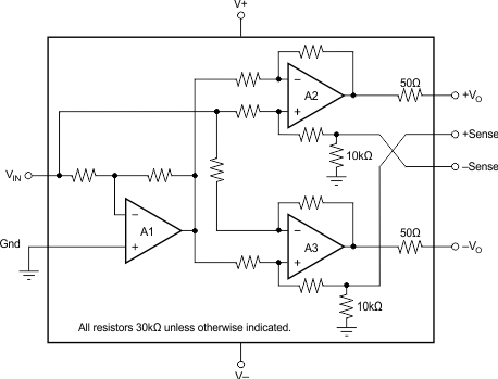
- 4 Simplified Schematic
- 5 Revision History
- 6 Pin Configuration and Functions
- 7 Specifications
- 8 Detailed Description
- 9 Application and Implementation
- 10Power Supply Recommendations
- 11Layout
- 12Device and Documentation Support
- 13Mechanical, Packaging, and Orderable Information
Package Options
Mechanical Data (Package|Pins)
- D|8
Thermal pad, mechanical data (Package|Pins)
Orderable Information
1 Features
- Balanced Output
- Low Distortion: 0.0005% at f = 1 kHz
- Wide Output Swing: 17Vrms into 600 Ω
- High Capacitive Load Drive
- High Slew Rate: 15 V/µs
- Wide Supply Range: ±4.5 V to ±18 V
- Low Quiescent Current: ±5.2 mA
- 8-Pin DIP, SO-8, and SOL-16 Packages
- Companion to Audio Differential Line Receivers: INA134 and INA137
- Improved Replacement for SSM2142
2 Applications
- Audio Differential Line Drivers
- Audio Mix Consoles
- Distribution Amplifiers
- Graphic and Parametric Equalizers
- Dynamic Range Processors
- Digital Effects Processors
- Telecom Systems
- Hi-Fi Equipment
- Industrial Instrumentation
3 Description
The DRV134 and DRV135 are differential output amplifiers that convert a single-ended input to a balanced output pair. These balanced audio drivers consist of high performance op amps with on-chip precision resistors. They are fully specified for high performance audio applications and have excellent ac specifications, including low distortion (0.0005% at 1 kHz) and high slew rate (15 V/µs).
The on-chip resistors are laser-trimmed for accurate gain and optimum output common-mode rejection. Wide output voltage swing and high output drive capability allow use in a wide variety of demanding applications. They easily drive the large capacitive loads associated with long audio cables. Used in combination with the INA134 or INA137 differential receivers, they offer a complete solution for transmitting analog audio signals without degradation.
The DRV134 is available in 8-pin DIP and SOL-16 surface-mount packages. The DRV135 comes in a space-saving SO-8 surface-mount package. Both are specified for operation over the extended industrial temperature range, –40°C to +85°C and operate from –55°C to +125°C.
Device Information(1)
| PART NUMBER | PACKAGE | BODY SIZE (NOM) |
|---|---|---|
| DRV134 | SOIC (16) | 10.30 mm × 7.50 mm |
| DRV135 | SOIC (8) | 4.90 mm × 3.91 mm |
- For all available packages, see the orderable addendum at the end of the datasheet.
4 Simplified Schematic
