SCAS859F January   2009  – June 2015 CDCLVP111

PRODUCTION DATA.  

  1. Features
  2. Applications
  3. Description
  4. Revision History
  5. Pin Configuration and Functions
  6. Specifications
    1. 6.1 Absolute Maximum Ratings
    2. 6.2 ESD Ratings
    3. 6.3 Recommended Operating Conditions
    4. 6.4 Thermal Information
    5. 6.5 DC Electrical Characteristics, LVECL
    6. 6.6 DC Electrical Characteristics, LVPECL
    7. 6.7 AC Electrical Characteristics
    8. 6.8 Typical Characteristics
  7. Parameter Measurement Information
    1. 7.1 Test Configurations
  8. Detailed Description
    1. 8.1 Overview
    2. 8.2 Functional Block Diagram
    3. 8.3 Feature Description
    4. 8.4 Device Functional Modes
  9. Applications and Implementation
    1. 9.1 Application Information
    2. 9.2 Typical Application
      1. 9.2.1 Fanout Buffer for Line Card Application
        1. 9.2.1.1 Design Requirements
        2. 9.2.1.2 Detailed Design Procedure
          1. 9.2.1.2.1 LVPECL Output Termination
          2. 9.2.1.2.2 Input Termination
        3. 9.2.1.3 Application Curves
  10. 10Power Supply Recommendations
    1. 10.1 Power-Supply Filtering
  11. 11Layout
    1. 11.1 Layout Guidelines
    2. 11.2 Layout Example
    3. 11.3 Thermal Management
  12. 12Device and Documentation Support
    1. 12.1 Documentation Support
      1. 12.1.1 Related Documentation
    2. 12.2 Community Resources
    3. 12.3 Trademarks
    4. 12.4 Electrostatic Discharge Caution
    5. 12.5 Glossary
  13. 13Mechanical, Packaging, and Orderable Information

パッケージ・オプション

メカニカル・データ(パッケージ|ピン)
サーマルパッド・メカニカル・データ
発注情報

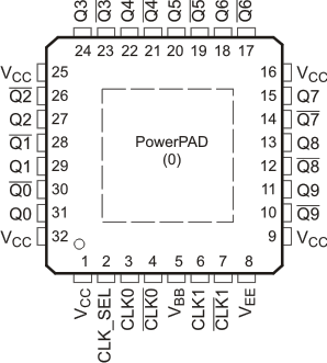
5 Pin Configuration and Functions

RHB, VF, or VFP Package
32-Pin VQFN, LQFP, or HLQFP
Top View
CDCLVP111 po_cas859.gif

Pin Functions(1)

PIN TYPE DESCRIPTION
NAME NO.
CLK_SEL 2 Input Clock select. Used to select between CLK0 and CLK1 input pairs. LVTTL/LVCMOS functionality compatible.
CLK0, CLK0 3 Input Differential LVECL/LVPECL input pair
4
CLK1, CLK1 6
7
Q [9:0] 11 Output LVECL/LVPECL clock outputs, these outputs provide low-skew copies of CLKn.
13
15
18
20
22
24
27
29
31
Q[9:0] 10 Output LVECL/LVPECL complementary clock outputs, these outputs provide copies of CLKn.
12
14
17
19
21
23
26
28
30
VBB 5 Reference voltage output for single-ended input operation
VCC 1 Power Supply voltage
9
16
25
32
VEE 8 Ground Device ground or negative supply voltage in ECL mode
PowerPAD™ 0 Ground The PowerPAD of the QFN32 is thermally connected to the die to improve the heat transfer out of the package. The pad of the QFN32 with PowerPAD must be connected to VEE.
(1) CLKn, CLK_SEL pulldown resistor = 75 kΩ; CLKn pullup resistor = 37.5 kΩ; CLKn pulldown resistor = 50 kΩ.