JAJSN53A February   2012  – December 2021 INA230

PRODUCTION DATA  

  1. 特長
  2. アプリケーション
  3. 概要
  4. Revision History
  5. Related Products
  6. Pin Configuration and Functions
  7. Specifications
    1. 7.1 Absolute Maximum Ratings
    2. 7.2 ESD Ratings
    3. 7.3 Recommended Operating Conditions
    4. 7.4 Thermal Information
    5. 7.5 Electrical Characteristics
    6. 7.6 Timing Requirements (I2C)
    7. 7.7 Typical Characteristics
  8. Detailed Description
    1. 8.1 Overview
    2. 8.2 Functional Block Diagram
    3. 8.3 Feature Description
      1. 8.3.1 Basic ADC Functions
      2. 8.3.2 Power Calculation
      3. 8.3.3 Alert Pin
    4. 8.4 Device Functional Modes
      1. 8.4.1 Averaging and Conversion Time Considerations
      2. 8.4.2 Filtering and Input Considerations
    5. 8.5 Programming
      1. 8.5.1 Programming the Calibration Register
      2. 8.5.2 Programming the INA230 Power Measurement Engine
        1. 8.5.2.1 Calibration Register and Scaling
      3. 8.5.3 Simple Current Shunt Monitor Usage (No Programming Necessary)
      4. 8.5.4 Default INA230 Settings
      5. 8.5.5 Bus Overview
        1. 8.5.5.1 Serial Bus Address
        2. 8.5.5.2 Serial Interface
      6. 8.5.6 Writing to and Reading From the I2C Serial Interface
        1. 8.5.6.1 High-Speed I2C Mode
      7. 8.5.7 SMBus Alert Response
    6. 8.6 Register Maps
      1. 8.6.1 Configuration Register (00h, Read/Write)
      2. 8.6.2 AVG Bit Settings [11:9]
      3. 8.6.3 VBUS CT Bit Settings [8:6]
      4. 8.6.4 VSH CT Bit Settings [5:3]
      5. 8.6.5 Mode Settings [2:0]
      6. 8.6.6 Data Output Register
        1. 8.6.6.1 Shunt Voltage Register (01h, Read-Only)
        2. 8.6.6.2 Bus Voltage Register (02h, Read-Only) (1)
        3. 8.6.6.3 Power Register (03h, Read-Only)
        4. 8.6.6.4 Current Register (04h, Read-Only)
        5. 8.6.6.5 Calibration Register (05h, Read/Write)
        6. 8.6.6.6 Mask/Enable Register (06h, Read/Write)
        7. 8.6.6.7 Alert Limit Register (07h, Read/Write)
  9. Application and Implementation
    1. 9.1 Application Information
    2. 9.2 Typical Applications
      1. 9.2.1 High-Side Sensing Circuit Application
        1. 9.2.1.1 Design Requirements
        2. 9.2.1.2 Detailed Design Procedure
        3. 9.2.1.3 Application Curves
  10. 10Power Supply Recommendations
  11. 11Layout
    1. 11.1 Layout Guidelines
    2. 11.2 Layout Example
  12. 12Device and Documentation Support
    1. 12.1 Documentation Support
      1. 12.1.1 Related Documentation
    2. 12.2 Receiving Notification of Documentation Updates
    3. 12.3 サポート・リソース
    4. 12.4 Trademarks
    5. 12.5 Electrostatic Discharge Caution
    6. 12.6 Glossary
  13. 13Mechanical, Packaging, and Orderable Information

パッケージ・オプション

メカニカル・データ(パッケージ|ピン)
サーマルパッド・メカニカル・データ
発注情報

概要

INA230 は I2C インターフェイス付きの電流シャント/電力モニタで、16 個のプログラマブル・アドレスを備えています。INA230 はシャント電圧降下とバス電源電圧の両方を監視します。較正値、変換時間、平均化オプションをプログラム可能で、内蔵のマルチプライヤと組み合わせて電流のアンペア値や電力のワット値を直接読み出すことができます。

INA230 は、0V~36V の範囲のバス電圧を検出できます。デバイスは 2.7V~5.5V の単一電源で動作し、消費電流は 330μA (標準値)です。INA230 は、-40℃~+125℃ の温度範囲で動作が規定されています。

製品情報(1)
部品番号パッケージ本体サイズ (公称)
INA230VQFN (16)3.00mm × 3.00mm
VSSOP (10)3.00mm × 3.00mm
利用可能なパッケージについては、このデータシートの末尾にある注文情報を参照してください。
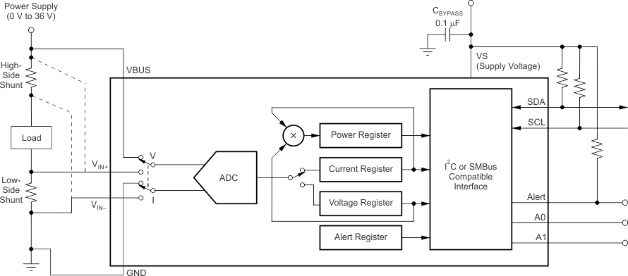
GUID-0CB56F43-C751-4E57-A357-9B6BB08FBAA1-low.gif代表的なアプリケーション