JAJSR58E January 2011 – August 2023 ISO3086T
PRODUCTION DATA
- 1
- 1 特長
- 2 アプリケーション
- 3 概要
- 4 Revision History
- 5 Pin Configuration and Functions
-
6 Specifications
- 6.1 Absolute Maximum Ratings
- 6.2 ESD Ratings
- 6.3 Recommended Operating Conditions
- 6.4 Thermal Information
- 6.5 Power Ratings
- 6.6 Insulation Specifications
- 6.7 Safety-Related Certifications
- 6.8 Safety Limiting Values
- 6.9 Electrical Characteristics: Driver
- 6.10 Electrical Characteristics: Receiver
- 6.11 Transformer Driver Characteristics
- 6.12 Supply Current
- 6.13 Switching Characteristics: Driver
- 6.14 Switching Characteristics: Receiver
- 6.15 Insulation Characteristics Curves
- 6.16 Typical Characteristics
- 7 Parameter Measurement Information
- 8 Detailed Description
- 9 Application and Implementation
- 10Power Supply Recommendations
- 11Layout
- 12Device and Documentation Support
- 13Mechanical, Packaging, and Orderable Information
パッケージ・オプション
メカニカル・データ(パッケージ|ピン)
- DW|16
サーマルパッド・メカニカル・データ
- DW|16
発注情報
9.2.2.1 Transient Voltages
Isolation of a circuit insulates it from other circuits and earth so that noise develops across the insulation rather than circuit components. The most common noise threat to data-line circuits is voltage surges or electrical fast transients that occur after installation and the transient ratings of the ISO3086T are sufficient for all but the most severe installations. However, some equipment manufacturers use their ESD generators to test transient susceptibility of their equipment and can easily exceed insulation ratings. ESD generators simulate static discharges that may occur during device or equipment handling with low-energy but very high voltage transients.
Figure 9-3 models the ISO3086T bus IO connected to a noise generator. CIN and RIN is the device and any other stray or added capacitance or resistance across the A or B pin to GND2, CISO and RISO is the capacitance and resistance between GND1 and GND2 of the ISO3086T plus those of any other insulation (transformer, etc.), and we assume stray inductance negligible. From this model, the voltage at the isolated bus return is shown in Equation 1 and will always be less than 16 V from VN.
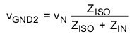
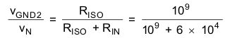
If the ISO3086T are tested as a stand-alone device, RIN= 6 × 10⁴Ω, CIN= 16 × 10-12 F, RISO= 109Ω and
CISO= 10-12 F.
In Figure 9-3 the resistor ratio determines the voltage ratio at low frequency and it is the inverse capacitance ratio at high frequency. In the stand-alone case and for low frequency, use Equation 2, or essentially all of noise appears across the barrier.
At very high frequency, Equation 3 is true, and 94% of VN appears across the barrier.
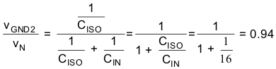
As long as RISO is greater than RIN and CISO is less than CIN, most of transient noise appears across the isolation barrier, as it should.
TI recommends not testing equipment transient susceptibility with ESD generators or consider product claims of ESD ratings above the barrier transient ratings of an isolated interface. ESD is best managed through recessing or covering connector pins in a conductive connector shell and installer training.
 Figure 9-3 Noise Model