JAJSLF6I October 2005 – June 2022 PCA9546A
PRODUCTION DATA
- 1 特長
- 2 アプリケーション
- 3 概要
- 4 Revision History
- 5 Pin Configuration and Functions
- 6 Specifications
- 7 Parameter Measurement Information
- 8 Detailed Description
- 9 Application Information Disclaimer
- 10Power Supply Recommendations
- 11Layout
- 12Device and Documentation Support
- 13Mechanical, Packaging, and Orderable Information
3 概要
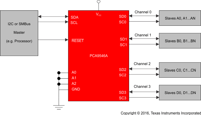
PCA9546A は、I2C バスで制御されるクワッド双方向変換スイッチです。SCL/SDA 上流ペアが、4 つの下流ペア (チャネル) に展開されます。プログラム可能な制御レジスタの設定により、どのような個別の SCn/SDn チャネルでも、あるいは、チャネルの組み合わせでも選択できます。
アクティブ LOW のリセット入力 (RESET) により、PCA9546A は下流の I2C バスの 1 つが LOW 状態に固着した状況から回復できます。RESET を LOW にすると、I2C ステート・マシンがリセットされ、すべてのチャネルが選択解除されます (内部のパワー・オン・リセット機能と同様)。
スイッチのパス・ゲートは、PCA9546A から印加される最大の HIGH 電圧を、VCC ピンを使用して制限できるように構成されています。これによって、ペアごとに異なるバス電圧を使用できるため、1.8V、2.5V、3.3V の部品が、追加保護の必要なしに 5V の部品と通信を行えます。外付けのプルアップ抵抗により、各チャネルに求められる電圧レベルにバスをプルアップします。すべての I/O ピンは 5.5V 許容です。
パッケージ情報
| 部品番号 | パッケージ(1) | 本体サイズ (公称) |
|---|---|---|
| PCA9546A | SOIC (D) (16) | 9.90mm × 3.91mm |
| TVSOP (DGV) (16) | 3.60mm × 4.40mm | |
| SOIC (DW) (16) | 10.3mm × 7.50mm | |
| TSSOP (PW) (16) | 5.00mm × 4.40mm | |
| VQFN (RGV) (16) | 4.00mm × 4.00mm | |
| VQFN (RGY) (16) | 4.50mm x 3.50mm |
(1) 利用可能なすべてのパッケージについては、このデータシートの末尾にある注文情報を参照してください。
 アプリケーション概略図