JAJSQU4 july 2023 TMUXHS221LV
PRODUCTION DATA
- 1
- 1 特長
- 2 アプリケーション
- 3 概要
- 4 Revision History
- 5 Pin Configuration and Functions
-
6 Specifications
- 6.1 Absolute Maximum Ratings
- 6.2 ESD Ratings
- 6.3 Recommended Operating Conditions
- 6.4 Thermal Information
- 6.5 Electrical Characteristics
- 6.6 High-Speed Performance Parameters
- 6.7 Switching Characteristics
- 6.8 Typical Characteristics – S-Parameters
- 6.9 Typical Characteristics – RON
- 6.10 Typical Characteristics – Eye Diagrams
- 18
- 7 Detailed Description
- 8 Application and Implementation
- 9 Device and Documentation Support
- 10Mechanical, Packaging, and Orderable Information
6.8 Typical Characteristics – S-Parameters
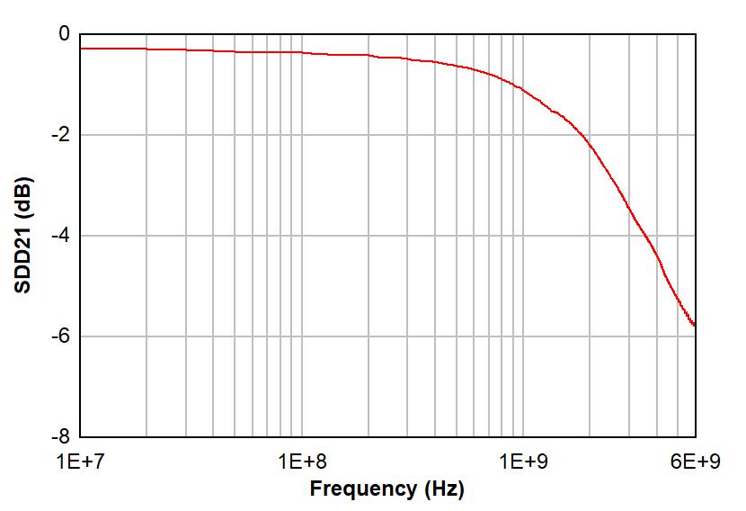
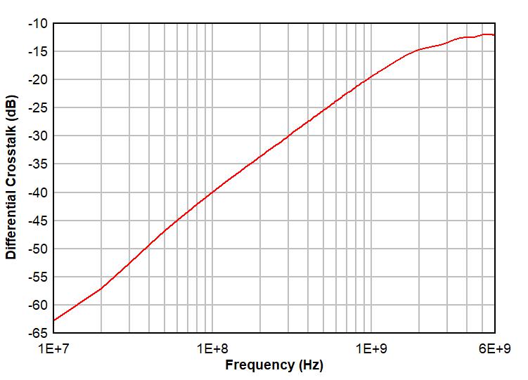
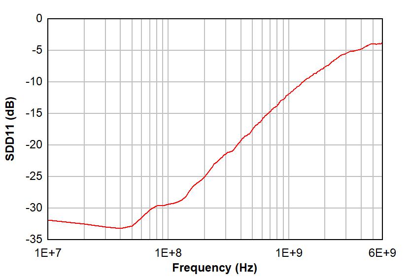
Figure 6-1 and Figure 6-2 show differential insertion loss and return loss for a typical TMUXHS221LV channel, respectively. The excellent high-speed performance at 240 MHz results in minimal attenuation to the USB 2.0 or eUSB2 HS signal eye diagrams. Figure 6-3 shows differential crosstalk for a typical TMUXHS221LV channel. Note, the measurements provided are performed in TI evaluation board with board and equipment parasitics calibrated out.
 Figure 6-1 Typical Differential Insertion Loss vs Frequency
 Figure 6-3 Typical Differential Crosstalk vs Frequency
 Figure 6-2 Typical Differential Return Loss vs Frequency