JAJSC06C SEPTEMBER 2013 – June 2018 TPS53513
PRODUCTION DATA.
- 1 特長
- 2 アプリケーション
- 3 概要
- 4 改訂履歴
- 5 Pin Configuration and Functions
- 6 Specifications
-
7 Detailed Description
- 7.1 Overview
- 7.2 Functional Block Diagram
- 7.3
Feature Description
- 7.3.1 5-V LDO and VREG Start-Up
- 7.3.2 Enable, Soft Start, and Mode Selection
- 7.3.3 Frequency Selection
- 7.3.4 D-CAP3 Control and Mode Selection
- 7.3.5 Power-Good
- 7.3.6 Current Sense and Overcurrent Protection
- 7.3.7 Overvoltage and Undervoltage Protection
- 7.3.8 Out-Of-Bounds Operation
- 7.3.9 UVLO Protection
- 7.3.10 Thermal Shutdown
- 7.4 Device Functional Modes
- 8 Application and Implementation
- 9 Power Supply Recommendations
- 10Layout
- 11デバイスおよびドキュメントのサポート
- 12メカニカル、パッケージ、および注文情報
パッケージ・オプション
メカニカル・データ(パッケージ|ピン)
- RVE|28
サーマルパッド・メカニカル・データ
- RVE|28
発注情報
7.3.4 D-CAP3 Control and Mode Selection
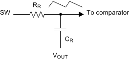
 Figure 34. Internal RAMP Generation Circuit
 The TPS53513 device uses D-CAP3 mode control to achieve fast load transient while maintaining the ease-of-use feature. An internal RAMP is generated and fed to the VFB pin to reduce jitter and maintain stability. The amplitude of the ramp is determined by the R-C time-constant as shown in Figure 34. At different switching frequencies, (fSW) the R-C time-constant varies to maintain relatively constant RAMP amplitude.