JAJSKK6A November   2020  – December 2021 TPS7H4010-SEP

PRODUCTION DATA  

  1. 特長
  2. アプリケーション
  3. 概要
  4. Revision History
  5. Pin Configuration and Functions
  6. Specifications
    1. 6.1 Absolute Maximum Ratings
    2. 6.2 ESD Ratings
    3. 6.3 Recommended Operating Conditions
    4. 6.4 Thermal Information
    5. 6.5 Electrical Characteristics
    6. 6.6 Timing Characteristics
    7. 6.7 Switching Characteristics
    8. 6.8 Typical Characteristics
  7. Detailed Description
    1. 7.1 Overview
    2. 7.2 Functional Block Diagram
    3. 7.3 Feature Description
      1. 7.3.1  Synchronous Step-Down Regulator
      2. 7.3.2  Auto Mode and FPWM Mode
      3. 7.3.3  Fixed-Frequency Peak Current-Mode Control
      4. 7.3.4  Adjustable Output Voltage
      5. 7.3.5  Enable and UVLO
      6. 7.3.6  Internal LDO, VCC_UVLO, and BIAS Input
      7. 7.3.7  Soft Start and Voltage Tracking
      8. 7.3.8  Adjustable Switching Frequency
      9. 7.3.9  Frequency Synchronization and Mode Setting
      10. 7.3.10 Internal Compensation and CFF
      11. 7.3.11 Bootstrap Capacitor and VBOOT-UVLO
      12. 7.3.12 Power-Good and Overvoltage Protection
      13. 7.3.13 Overcurrent and Short-Circuit Protection
      14. 7.3.14 Thermal Shutdown
    4. 7.4 Device Functional Modes
      1. 7.4.1 Shutdown Mode
      2. 7.4.2 Standby Mode
      3. 7.4.3 Active Mode
        1. 7.4.3.1 CCM Mode
        2. 7.4.3.2 DCM Mode
        3. 7.4.3.3 PFM Mode
        4. 7.4.3.4 Fault Protection Mode
  8. Application and Implementation
    1. 8.1 Application Information
    2. 8.2 Typical Application
      1. 8.2.1 Design Requirements
      2. 8.2.2 Detailed Design Procedure
        1. 8.2.2.1  Output Voltage Setpoint
        2. 8.2.2.2  Switching Frequency
        3. 8.2.2.3  Input Capacitors
        4. 8.2.2.4  Inductor Selection
        5. 8.2.2.5  Output Capacitor Selection
        6. 8.2.2.6  Feed-Forward Capacitor
        7. 8.2.2.7  Bootstrap Capacitors
        8. 8.2.2.8  VCC Capacitor
        9. 8.2.2.9  BIAS
        10. 8.2.2.10 Soft Start
        11. 8.2.2.11 Undervoltage Lockout Setpoint
        12. 8.2.2.12 PGOOD
      3. 8.2.3 Application Curves
  9. Power Supply Recommendations
  10. 10Layout
    1. 10.1 Layout Guidelines
      1. 10.1.1 Layout For EMI Reduction
      2. 10.1.2 Ground Plane
      3. 10.1.3 Optimize Thermal Performance
    2. 10.2 Layout Example
  11. 11Device and Documentation Support
    1. 11.1 Device Support
      1. 11.1.1 Third-Party Products Disclaimer
    2. 11.2 Related Documentation
    3. 11.3 Receiving Notification of Documentation Updates
    4. 11.4 サポート・リソース
    5. 11.5 Trademarks
    6. 11.6 Electrostatic Discharge Caution
    7. 11.7 Glossary
  12. 12Mechanical, Packaging, and Orderable Information

パッケージ・オプション

デバイスごとのパッケージ図は、PDF版データシートをご参照ください。

メカニカル・データ(パッケージ|ピン)
  • RNP|30
  • KGD|0
サーマルパッド・メカニカル・データ
発注情報

Application Curves

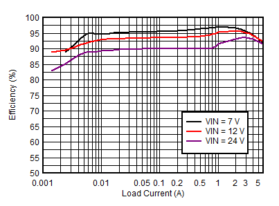
GUID-9F8BAB7C-B2EA-47E9-A843-200E0D5A7FEA-low.gif
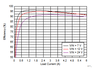
VOUT = 5 VfSW = 500 kHzAuto Mode
Figure 8-3 TPS7H4010-SEP Efficiency
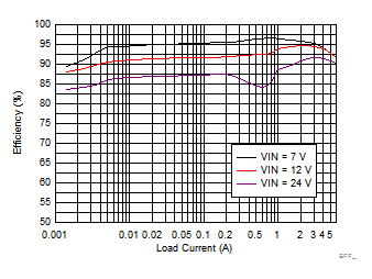
GUID-CC2EA103-F826-41C4-8A90-2B94992FD172-low.gif
VOUT = 5 VfSW = 1000 kHzAuto Mode
Figure 8-5 TPS7H4010-SEP Efficiency
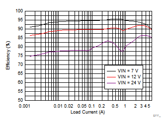
GUID-6933ACD6-AABE-46FC-8E7D-AEA3CA9CB8AD-low.gif
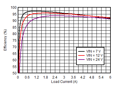
VOUT = 5 VfSW = 2200 kHzAuto Mode
Figure 8-7 TPS7H4010-SEP Efficiency
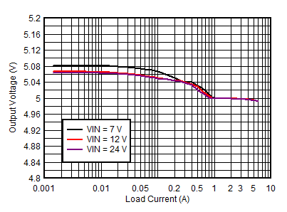
GUID-77B1FA3D-189A-417A-800D-1684A8379375-low.gif
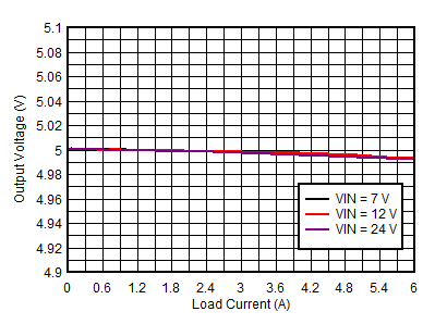
VOUT = 5 VfSW = 500 kHzAuto Mode
Figure 8-9 TPS7H4010-SEP Load and Line Regulation
GUID-627C2CC9-E464-4D14-84A8-6D5239419357-low.gif
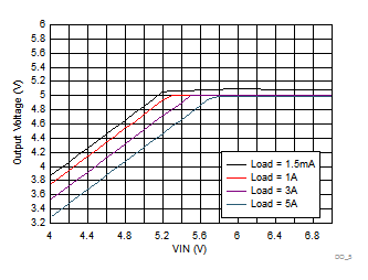
VOUT = 5 VfSW = 2200 kHzAuto Mode
Figure 8-11 TPS7H4010-SEP Dropout Curve
GUID-215BAC8E-8E3A-4F2C-818A-21F6DC30A5F2-low.gif
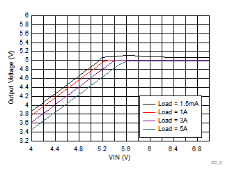
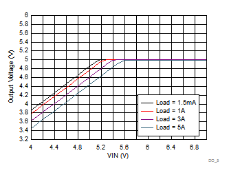
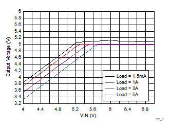
VOUT = 5 VfSW = 500 kHzAuto Mode
Figure 8-13 TPS7H4010-SEP Dropout Curve
GUID-F9F6618D-13E1-4266-BF5D-7188EF0ED073-low.gif
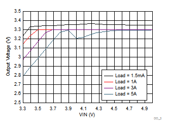
VOUT = 3.3 VfSW = 500 kHzAuto Mode
Figure 8-15 TPS7H4010-SEP Dropout Curve
GUID-230C7BA6-828D-4D16-BA7C-916EA6BF2DE0-low.gif
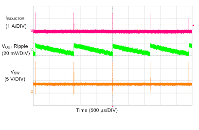
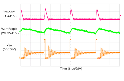
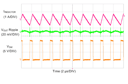
VIN = 12 VVOUT = 3.3 VfSW = 500 kHz
IOUT = 1 mAAuto Mode
Figure 8-17 TPS7H4010-SEP Switching Waveform and VOUT Ripple
GUID-5BE42A17-BFAC-4F30-9465-FA58A01A6C76-low.gif
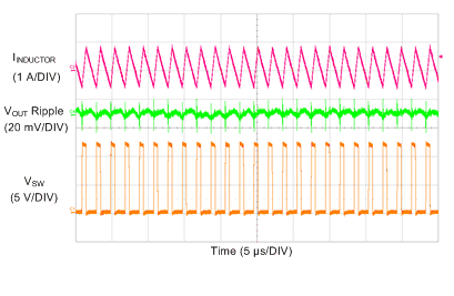
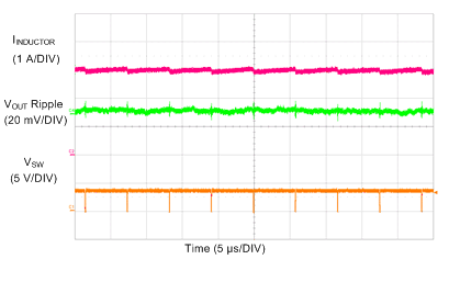
VIN = 12 VVOUT = 3.3 VfSW = 500 kHz
IOUT = 100 mAAuto Mode
Figure 8-19 TPS7H4010-SEP Switching Waveform and VOUT Ripple
GUID-87A84AEF-BCBD-4F84-833A-A3C6E315BF52-low.gif
VIN = 12 VVOUT = 3.3 VfSW = 500 kHz
IOUT = 6 AAuto Mode
Figure 8-21 TPS7H4010-SEP Switching Waveform and VOUT Ripple
GUID-C21BB13D-C558-49AC-A72E-2B155858A74A-low.gif
VIN = 12 VVOUT set at 3.3 VfSW set at 500 kHz
IOUT = 7.5 AVOUT droops to 2 V
Figure 8-23 TPS7H4010-SEP Overcurrent Behavior
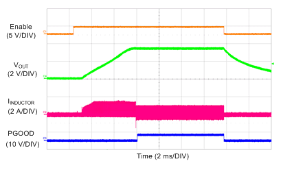
GUID-B560D4DF-9B92-4FEC-9FCB-2FBE8CBD62B8-low.gif
VIN = 12 VVOUT = 3.3 VfSW = 500 kHz
IOUT= 200 mAFPWM Mode
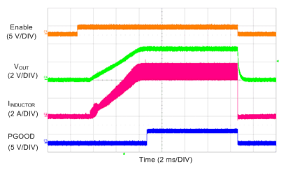
Figure 8-25 TPS7H4010-SEP Soft Start With 200-mA Load in FPWM Mode
GUID-9D5765AE-80A7-420F-A5B5-9C316DA7EFC0-low.gif
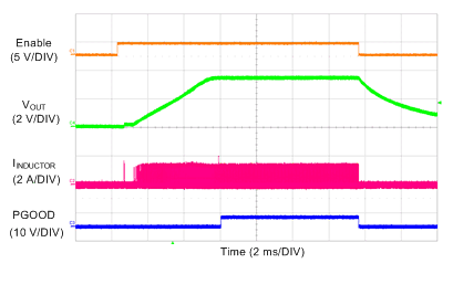
VIN = 12 VVOUT = 3.3 VfSW = 500 kHz
IOUT = 5 AAuto Mode
Figure 8-27 TPS7H4010-SEP Soft Start With 5-A Load
GUID-84633DEE-1F0B-4EC4-8240-2121F4495CCE-low.gif
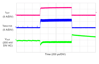
VIN = 12 VVOUT = 3.3 VfSW = 500 kHz
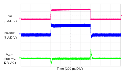
IOUT = 10 mA to 6 A to 10 mAAuto Mode
Figure 8-29 TPS7H4010-SEP Load Transients
GUID-8A541AF8-218B-465D-9744-A2DB80F0EDAF-low.gif
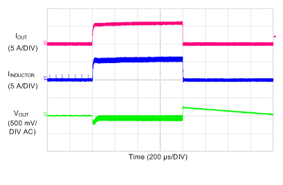
VIN = 12 VVOUT = 5 VfSW = 2200 kHz
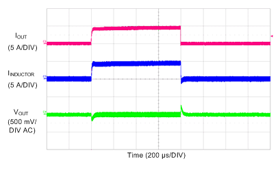
IOUT = 10 mA to 5 A to 10 mAAuto Mode
Figure 8-31 TPS7H4010-SEP Load Transients
GUID-9653C1E1-B5C7-4C5A-BFBF-DA1691D75D2A-low.gif
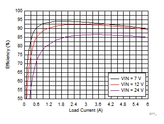
VOUT = 5 VfSW = 500 kHzFPWM Mode
Figure 8-4 TPS7H4010-SEP Efficiency
GUID-8C32F765-4C2E-49A7-9C01-6483079C7455-low.gif
VOUT = 5 VfSW = 1000 kHzFPWM Mode
Figure 8-6 TPS7H4010-SEP Efficiency
GUID-4ABA2233-FBC5-493C-AA35-FD9E19B8E2BD-low.gif
VOUT = 5 VfSW = 2200 kHzFPWM Mode
Figure 8-8 TPS7H4010-SEP Efficiency
GUID-387E6916-883A-4536-AF04-AC2A1366BF74-low.gif
VOUT = 5 VfSW = 500 kHzFPWM Mode
Figure 8-10 TPS7H4010-SEP Load and Line Regulation
GUID-C0BB6ECE-E6B3-4E69-B3BC-C5FF959E8929-low.gif
VOUT = 5 VfSW = 2200 kHzFPWM Mode
Figure 8-12 TPS7H4010-SEP Dropout Curve
GUID-7D383189-D8F9-4754-8B23-1B6BA5BB60A2-low.gif
VOUT = 5 VfSW = 1000 kHzAuto Mode
Figure 8-14 TPS7H4010-SEP Dropout Curve
GUID-86A04D54-2C90-4ED2-8E4D-6B85C4B6A3D6-low.gif
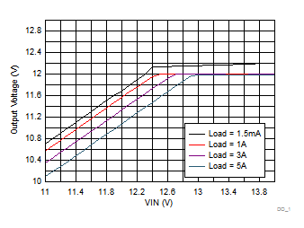
VOUT = 12 VfSW = 500 kHzAuto Mode
Figure 8-16 TPS7H4010-SEP Dropout Curve
GUID-1B051C2D-DBE1-470F-A472-63DF58A930A7-low.gif
VIN = 12 VVOUT = 3.3 VfSW = 500 kHz
IOUT = 1 mAFPWM Mode
Figure 8-18 TPS7H4010-SEP Switching Waveform and VOUT Ripple
GUID-0F6290C8-893E-40C2-8B3E-8DBBF71BB11C-low.gif
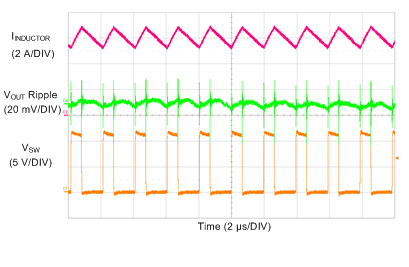
VIN = 12 VVOUT = 3.3 VfSW = 500 kHz
IOUT = 100 mAFPWM Mode
Figure 8-20 TPS7H4010-SEP Switching Waveform and VOUT Ripple
GUID-5119AA65-B81A-49C3-93BC-6BA8A87FCF49-low.gif
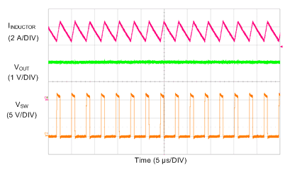
VIN = 3.66 VVOUT = 3.3 VfSW set at 500 kHz
IOUT = 3 AAuto Mode
Figure 8-22 TPS7H4010-SEP Switching Waveform at Dropout
GUID-1EF4DF32-AD31-4F04-9D07-55A691757350-low.gif
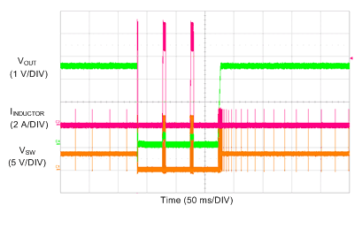
VIN = 12 VVOUT = 3.3 VfSW = 500 kHz
Figure 8-24 TPS7H4010-SEP Short-Circuit Hiccup Protection and Recovery
GUID-1BD7E204-0956-4A72-8144-F20AD5601831-low.gif
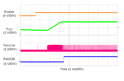
VIN = 12 VVOUT = 3.3 VfSW = 500 kHz
IOUT= 200 mAAuto Mode
Figure 8-26 TPS7H4010-SEP Soft Start With 200-mA Load in Auto Mode
GUID-6552C8B1-66B9-468A-B062-DE99E0818926-low.gif
VIN = 12 VVOUT = 3.3 VfSW = 500 kHz
VPRE-BIAS= 1.5 VAuto Mode
Figure 8-28 TPS7H4010-SEP Soft Start With Pre-Biased Output Voltage
GUID-C38FFF21-A4C8-4E5B-8C1D-0FF22AAE3270-low.gif
VIN = 12 VVOUT = 3.3 VfSW = 500 kHz
IOUT = 10 mA to 6 A to 10 mAFPWM Mode
Figure 8-30 TPS7H4010-SEP Load Transients
GUID-1B5ECE10-CF8A-4671-A84E-F58D68DAFCD1-low.gif
VIN = 12 VVOUT = 5 VfSW = 2200 kHz
IOUT = 10 mA to 5 A to 10 mAFPWM Mode
Figure 8-32 TPS7H4010-SEP Load Transients