JAJSHP9E November 2007 – July 2019 VCA824
PRODUCTION DATA.
- 1 特長
- 2 アプリケーション
- 3 概要
- 4 改訂履歴
- 5 Device Comparison Table
- 6 Pin Configuration and Functions
-
7 Specifications
- 7.1 Absolute Maximum Ratings
- 7.2 ESD Ratings
- 7.3 Recommended Operating Conditions
- 7.4 Thermal Information
- 7.5 Electrical Characteristics: VS = ±5 V
- 7.6 Typical Characteristics: VS = ±5 V, AVMAX = 2 V/V
- 7.7 Typical Characteristics: VS = ±5 V, AVMAX = 10 V/V
- 7.8 Typical Characteristics: VS = ±5 V, AVMAX = 40 V/V
- 8 Detailed Description
- 9 Application and Implementation
- 10Power Supply Recommendations
- 11Layout
- 12デバイスおよびドキュメントのサポート
- 13メカニカル、パッケージ、および注文情報
パッケージ・オプション
メカニカル・データ(パッケージ|ピン)
サーマルパッド・メカニカル・データ
- D|14
発注情報
9.1.3 Differential Cable Equalizer
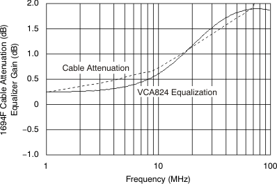
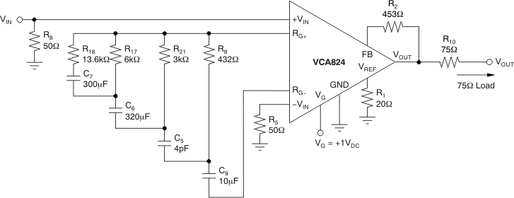
A differential cable equalizer can easily be implemented using the VCA824. An example of a cable equalization for 100 feet of Belden Cable 1694F is illustrated in Figure 73, with Figure 72 showing the result for this implementation. This implementation has a maximum error of 0.2 dB from DC to 70 MHz.
 Figure 72. Cable Attenuation vs Equalizer Gain
 Note that this implementation shows the cable attenuation side-by-side with the equalization in the same plot. For a given frequency, the equalization function realized with the VCA824 matches the cable attenuation. The circuit in Figure 73 is a driver circuit. To implement a receiver circuit, the signal is received differentially between the +VIN and –VIN inputs.
 Figure 73. Differential Cable Equalizer