DLPA078B February 2017 – September 2021 DLP160AP , DLP160CP , DLP2000 , DLP2010 , DLP230GP , DLP230KP , DLP230NP , DLP3010 , DLP3310 , DLP4710 , DLP471TP , DLPC3420 , DLPC3421
- Trademarks
- 1 Introduction to Optical Modules
- 2 Use Case Considerations
- 3 Core Optical Module Specifications
- 4 Additional Optical Module Specifications
- 5 Features Implemented in Software
- 6 Hardware Integration Considerations
- 7 Business Considerations
- 8 Example Optical Module Specification Table
- 9 Get Started with Development
- 10Revision History
1.5 Flash Memory Board
The flash memory board is a small board typically attached to either the module itself or the flex cable connecting the DMD and DLP controller. DLP image processing settings specific to the optical module are stored in the flash memory and are used by the DLP controller during configuration of the system.
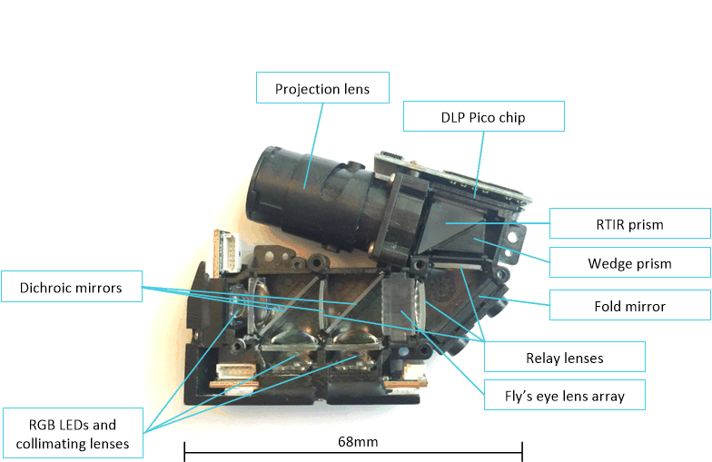
 Figure 1-2 Optical Components in an
Example Pico Projection Optical Module Dimensions: 68×57×15
mm3
Figure 1-2 Optical Components in an
Example Pico Projection Optical Module Dimensions: 68×57×15
mm3TI manufactures and sells the DLP chipset, which includes a DMD, a controller IC, and a power management IC (PMIC). Of these three components, only the DMD is included in an optical module (the controller and PMIC are integrated on a nearby printed circuit board or PCB).
TI offers a portfolio of DMDs that enable different classes of optical modules (see the DLP Display & Projection Chipset Selection Guide). Optical modules are designed and manufactured by third party companies (see Figure 1-3). Customers can source a pre-existing, tooled optical module from an optical module manufacturer (OMM) to speed design time and get to market faster. Alternatively, custom optical modules can be designed by an OMM with additional time and resources. The optical module ecosystem is robust, with OMMs worldwide that can supply a variety of optical modules in high volumes.
 Figure 1-3 Supply Chain from TI DLP Chip
to Product