JAJU633 October 2018
- 概要
- リソース
- 特長
- アプリケーション
- デザイン・イメージ
- 1System Description
-
2System Overview
- 2.1 Block Diagram
- 2.2 Highlighted Products
- 2.3 LM74700
- 2.4
System Design Theory
- 2.4.1
Design Procedure
- 2.4.1.1 Operating Parameters, Duty Cycle
- 2.4.1.2 Setting the Switching Frequency
- 2.4.1.3 Inductor Value Calculation
- 2.4.1.4 Peak Inductor Current
- 2.4.1.5 Calculating RIS (R9)
- 2.4.1.6 Minimum Output Capacitance
- 2.4.1.7 Setting the LED Current
- 2.4.1.8 Soft-Start Capacitor
- 2.4.1.9 Overvoltage Protection (OVP)
- 2.4.1.10 Main N-Channel MOSFET Selection
- 2.4.1.11 Rectifier Diode Selection
- 2.4.1.12 Thermal Protection
- 2.4.2 Designing for Low EMI
- 2.4.1
Design Procedure
- 3Hardware, Software, Testing Requirements, and Test Results
- 4Design Files
- 5Related Documentation
2.2.1 TPS92692-Q1
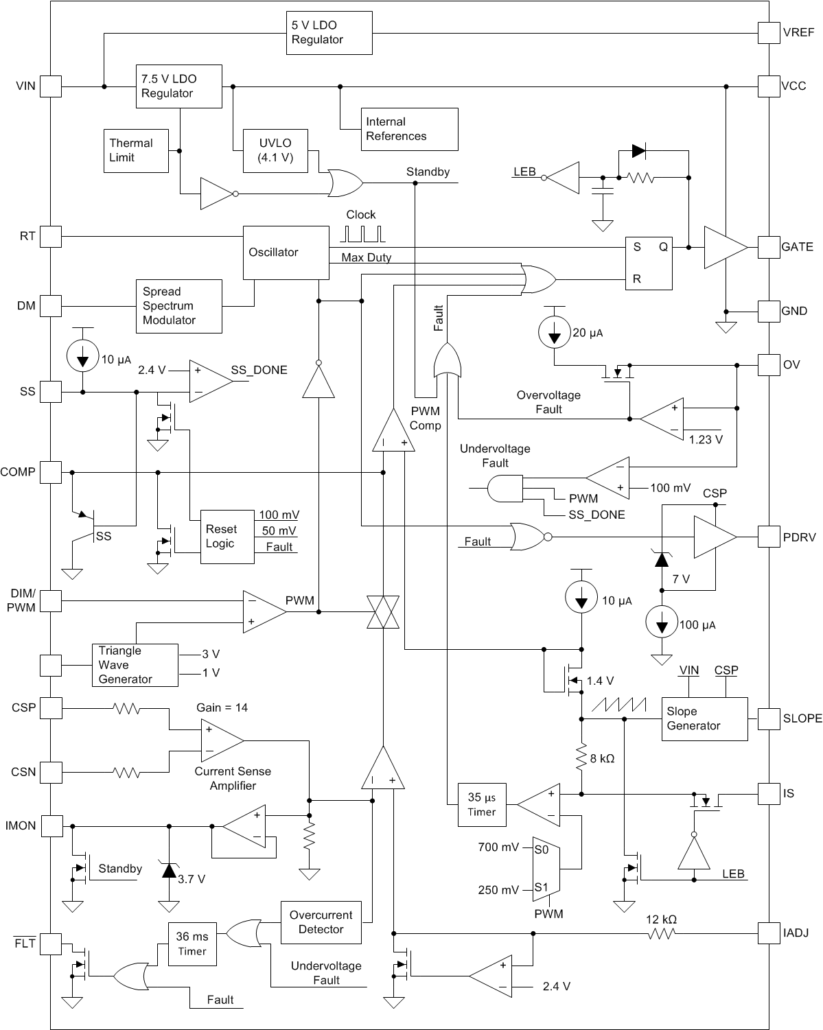
The TPS92692 device is a versatile LED controller that can support a range of topologies. The device is intended for high-brightness LED lighting applications where efficiency, high accuracy, high power, and PWM or analog dimming (or both) are important. The device includes a gate driver for an external LED string disconnect FET to enable faster turn-on and turn-off of the LED string for high contrast ratios. In addition, it has the capability for Spread Spectrum Frequency Modulation for improved EMI performance.
A low-offset rail-to-rail current sense amplifier imporves the steady-state accuracy. This amplifier directly measures LED current using either a high-side or a low-side series current sense resistor. The device modulates LED current using either analog dimming, PWM dimming, or both simultaneously. Other features include undervoltage lockout (UVLO), wide input voltage operation, open and over-voltage protection (OVP) operation, and wide-operating temperature range with thermal shutdown.
 Figure 3. TPS92692 Block Diagram
 The TPS92692 device operates at an input range up to 65 V in a thermally enhanced 20-pin HTSSOP package.
Key features of this device include:
- Wide input voltage range: 4.5 V to 65 V
- Low input offset rail-to-rail current sense amplifier:
- Better than ±4% LED current accuracy over -40°C to 150°C junction temperature range
- Compatible with high-side and low-side current sense implementations
- High-impedance analog LED current adjust input (IADJ) with over 15:1 contrast ratio
- Over 1000:1 series FET PWM dimming ratio with integrated series P-Channel dim driver interface
- Spread Spectrum Frequency Modulation for Improved EMI
- Continuous LED current monitor output for system fault detection and diagnoses
- Programmable switching frequency with external clock synchronization capability
- Programmable soft-start and adaptive slope compensation
- Comprehensive fault protection circuitry including VCC UVLO, output OVP, cycle-by-cycle switch current limit, and thermal protection
- TPS92692-Q1: Automotive Q100 Grade 1 qualified