SBAA377B April 2022 – January 2024 PCM3120-Q1 , PCM5120-Q1 , PCM6120-Q1 , TLV320ADC3120 , TLV320ADC3140 , TLV320ADC5120 , TLV320ADC5140 , TLV320ADC6120 , TLV320ADC6140
3.1.2 Low-Latency Filters
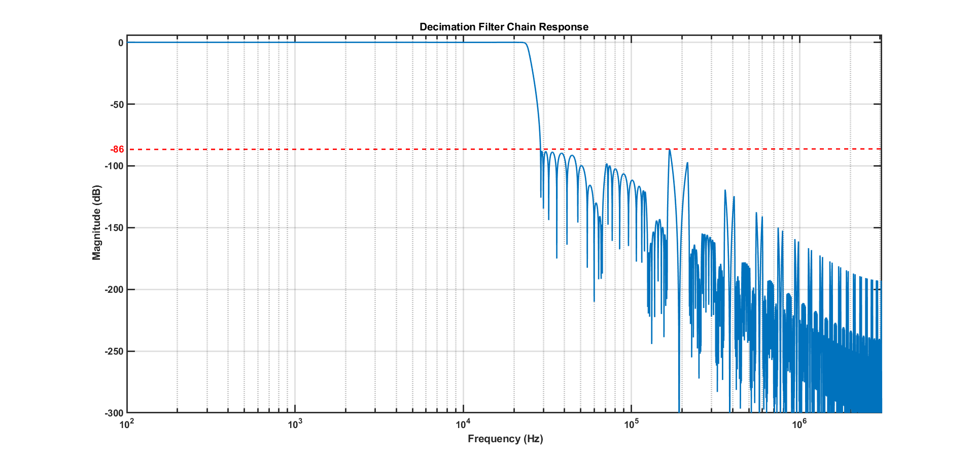
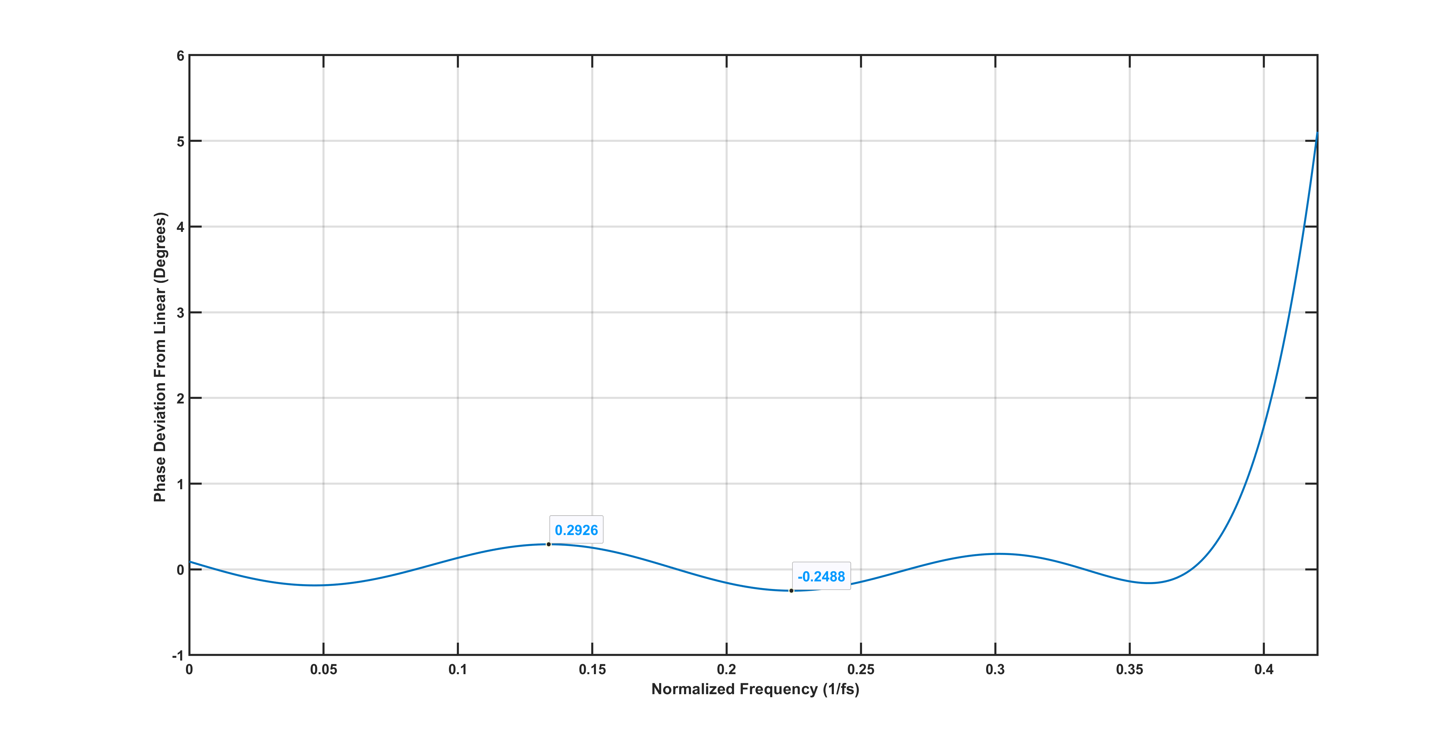
Low-latency decimation filters have smaller group delay (around 5–7 samples at the output sample rate) than the linear phase filters but have non-zero group delay deviation. The group delay deviation is typically less than one-hundredth the time period of the output sampling rate. The out-of-band attenuation is greater than 85 dB for low-latency filters across all sample rates. Figure 3-2 shows the low-latency response for the 48-kHz sample rates for reference. The dashed line indicates the minimum out-of-band attenuation level, which is around 86 dB. This implies that the strength of any aliased out-of-band noise component would be attenuated by at least 86 dB by the low-latency decimation filter chain. Low-latency filters are suitable for applications requiring fast analog-to-digital conversion and process the low- and mid-frequency bands. Figure 3-3 shows the phase deviation plot of the 48 kHz low-latency filter. It has a near-zero (less than 0.3 degrees and greater than -0.25 degrees) phase deviation from DC to 0.37 × fs Hz. Applications that has a band of interest is less than 0.37 × fs Hz can use the low-latency filters and take advantage of the faster conversion.
 Figure 3-2 Low-Latency Decimation Filter
Response
 Figure 3-3 Phase Deviation of Low-Latency
Decimation Filter