SBAU443 November 2023
3.2.1 Configuring the Audio Serial Bus for the I2S Output
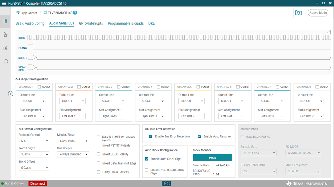
The PCMx140Q1 features a highly flexible audio serial bus that can be configured to implement a wide range of data formats. The default format is TDM, however the GUI can be used to change the data format to I2S. This section describes how to configure the PCMx140Q1EVM for a 2-channel I2S output to a USB audio at 16 bits and 48 kHz. Configure the AC-MB for USB audio as described in Section 3.2. As shown in Figure 4-10, select the audio serial bus tab.
 Figure 3-10 Audio Serial Bus Tab
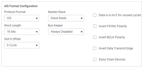
In the ASI format configuration pane (shown in Figure 4-11), change the protocol format to I2S, and the word length to 16 bits.
 Figure 3-11 ASI Format
Configuration
Figure 3-11 ASI Format
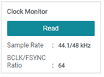
ConfigurationWhen the protocol format is changed to I2S in the GUI, the USB audio processor on the AC-MB also changes the audio format to I2S. The GUI reads the ASI status register (page 0 register 0x15), providing the detected sampling rate and BCLK and FSYNC ratio. The ASI status register can also be read manually in the audio serial bus tab by clicking the Read button, as shown in Figure 4-12, in the clock monitor pane.
 Figure 3-12 Clock Monitor Pane
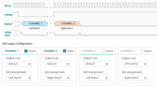
The default slot assignment for channel 1 is left slot 0 and the default slot assignment for channel 2 is left slot 1. As shown in Figure 4-13, change the channel 2 slot assignment to right slot 0. The diagram at the top of the window updates to display the data format and slots selected.
 Figure 3-13 Channel Output Configuration
and Diagram