SBAU443 November   2023


  1.   1
  2.   Description
  3.   Get Started
  4.   Features
  5.   Applications
  6.   6
  7. 1Evaluation Module Overview
    1. 1.1 Introduction
    2. 1.2 Kit Contents
    3. 1.3 Specification
    4. 1.4 Device Information
  8. 2Hardware
    1. 2.1 System Overview
    2. 2.2 Hardware Overview
      1. 2.2.1 AC-MB Settings
        1. 2.2.1.1 Audio Serial Interface Settings
          1. 2.2.1.1.1 USB
          2. 2.2.1.1.2 18
          3. 2.2.1.1.3 Optical or Auxiliary Analog Audio Input
          4. 2.2.1.1.4 External
        2. 2.2.1.2 AC-MB Power Supply
      2. 2.2.2 PCMx140Q1EVM-PDK Hardware Settings
        1. 2.2.2.1 Line Inputs
        2. 2.2.2.2 Onboard Microphone Input
  9. 3Software
    1. 3.1 Software Overview
      1. 3.1.1 PurePath Console 3 Installation
      2. 3.1.2 PCMx140Q1EVM GUI Installation
        1. 3.1.2.1 Software Setup
    2. 3.2 Quick Start
      1. 3.2.1 Configuring the Audio Serial Bus for the I2S Output
      2. 3.2.2 32
      3. 3.2.3 Saving a Configuration
    3. 3.3 Matlab Audio Capture Example
  10. 4Hardware Design Files
    1. 4.1 PCMx140Q1EVM-PDK Schematic and Bill of Materials
      1. 4.1.1 PCMx140Q1EVM-PDK Schematic
      2. 4.1.2 PCB Layouts
      3. 4.1.3 PCMx140Q1EVM-PDK Bill of Materials
    2. 4.2 AC-MB Schematic and Bill of Materials
      1. 4.2.1 AC-MB Schematic
      2. 4.2.2 PCB Layouts
      3. 4.2.3 AC-MB Bill of Materials
  11. 5Additional Information
    1. 5.1 Trademarks
  12. 6Related Documentation

Quick Start

Configure the AC-MB for the USB audio (TDM) and the PCMx140Q1EVM for the onboard microphone input.

All configurations for this example are done on the audio configuration tab. In the Audio Configuration block in the lower right portion of the audio configuration tab (as shown in Figure 4-6), select a word length of 16 bits, and enable the ASI output channel 1.
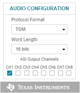
GUID-018792D6-547A-42BF-A610-C37D72FDD089-low.gif Figure 3-6 Audio Configuration

As shown in Figure 4-7, select AVDD for the MIC bias voltage and power-up the MIC bias.
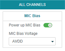
GUID-F4A03698-E1B1-43FD-8ED2-B1F426EC6F9E-low.gif Figure 3-7 MIC Bias Configuration

The default state for the PCMx140Q1 is standby mode and, with the exception of the channel digital volume, all device configurations must be done in standby mode. The PCMx140Q1 does not provide a digital audio output in standby mode. Figure 4-8 shows how to change the mode from standby to active.

GUID-20689C15-DF99-4A1B-83F8-0720157E3943-low.gif Figure 3-8 Standby to Active Mode

When active mode is enabled, any controls not configurable in active mode are grayed out. These controls can be changed again when the device is brought out of active mode. Figure 4-9 shows which controls are disabled.
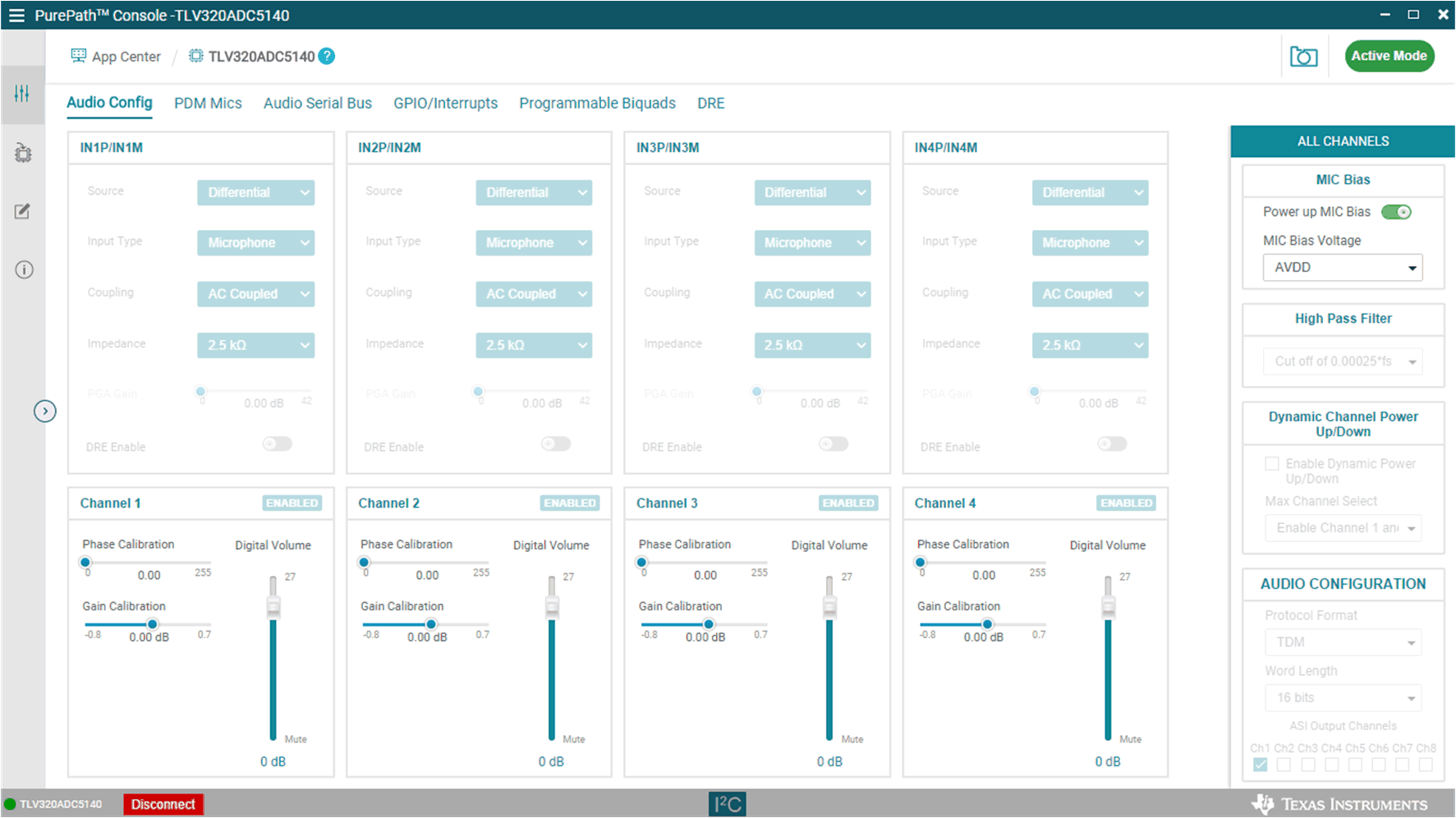
GUID-824D66A5-6A2A-4D37-B231-5EA8A4F0D625-low.gif Figure 3-9 Disabled Controls in Active Mode

Audio can now be captured on your PC using the audio program of your choice.