SBOA444 November 2020 TMCS1100
4.2.1.2 Power Quality Formulas
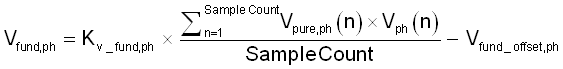
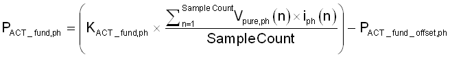
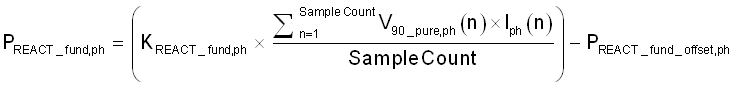
For calculating the fundamental RMS voltage, a pure sine wave is generated and tightly locked to the fundamental of the incoming voltage waveform. Using the generated waveform, the fundamental voltage, fundamental active power, and fundamental reactive power are calculated by the following equations:
Where,
Vpure,ph(n) = Voltage sample of the pure sine wave generated, taken at a sample instant n
V90_pure,ph(n) = Voltage sample of the waveform that results from shifting Vpure,ph(n) by 90° , taken at a sample instant n
Kv_fund,ph = Scaling factor for fundamental voltage
KACT_fund,ph = Scaling factor for fundamental active power
KREACT_fund,ph = Scaling factor for fundamental active power
Vfund_offset_,ph= Offset to subtract from fundamental voltage calculation. This is in units of mV.
PACT_fund_offset,ph = Offset to subtract from fundamental active power calculation. This is in units of mW.
PREACT_fund_offset,ph = Offset to subtract from fundamental reactive power calculation. This is in units of mvar.
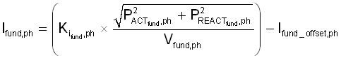
After calculating the fundamental voltage, fundamental active power, and fundamental reactive power, the fundamental current and fundamental apparent power are calculated by the following formula:
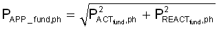
Where,
Ki_fund,ph = Scaling factor for fundamental current
Ifund_offset_,ph= Offset to subtract from fundamental current calculation. This is in units of µA.
Once the fundamental current and fundamental voltage are calculated, the voltage THD and current THD can also be calculated. This software supports three different methods of calculating THD that are referred to as THDIEC_F, THDIEC_R, and THDIEEE. The formulas used to calculate voltage THD (V_THD) and current THD (I_THD) with the different methods as follows:
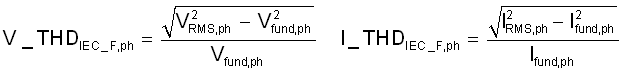
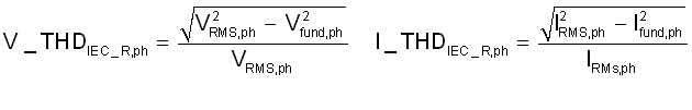
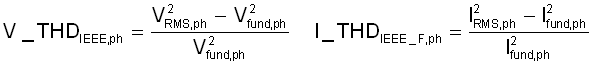
To calculate THD correctly, it is necessary to select the proper method of THD calculation and to ensure that any reference meter used for measuring THD uses the same THD method as the method selected in software.