SBOU293D November   2022  – January 2024


  1.   1
  2.   Abstract
  3.   Trademarks
  4. 1Overview
    1. 1.1 OPTEVM Kit Contents
    2. 1.2 Related Documentation from Texas Instruments
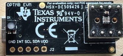
  5. 2OPTEVM Hardware Overview
  6. 3OPTEVM Software
    1. 3.1 Hardware Requirements
    2. 3.2 Software Installation
    3. 3.3 Typical OPTEVM Hardware Setup
    4. 3.4 Launching the OPT300x/4xxxEVM Software
    5. 3.5 OPTEVM Software Operation
      1. 3.5.1 Getting Started
      2. 3.5.2 Feature Descriptions
        1. 3.5.2.1 Lux Plot
        2. 3.5.2.2 Mean, Std, and the Blue Slider
    6. 3.6 Controls
      1. 3.6.1 Capture Controls
        1. 3.6.1.1 Start Capture and Stop Capture
        2. 3.6.1.2 Display Sample Count
        3. 3.6.1.3 Save to File
      2. 3.6.2 Device Controls
        1. 3.6.2.1 Mode Select
        2. 3.6.2.2 Conversion Time
      3. 3.6.3 Operation Controls
        1. 3.6.3.1 Operation Select
        2. 3.6.3.2 Measurement/Capture Trigger
        3. 3.6.3.3 Oneshot Time (μs)
    7. 3.7 OPTxxxDTSEVM Variants
      1. 3.7.1 OPT4048DTSEVM
        1. 3.7.1.1 OPT4048DTSEVM CIE XY Window
        2. 3.7.1.2 OPT4048DTSEVM Lux Live Window
        3. 3.7.1.3 OPT4048DTSEVM Channel Live Window
      2. 3.7.2 OPT4060DTSEVM
        1. 3.7.2.1 OPT4060DTSEVM Channel Live Window
        2. 3.7.2.2 OPT4060DTSEVM Lux Live Window
    8. 3.8 Scripts Window
      1. 3.8.1 Additional Features of the Scripts Window
        1. 3.8.1.1 Hidden IDE Window
        2. 3.8.1.2 devInit.py
        3. 3.8.1.3 04-launchGUI.py
      2. 3.8.2 Overview of Device Registers: OPT4xxx Devices
  7. 4Schematic, PCB Layout, and Bill of Materials
    1. 4.1 Coupon Board
      1. 4.1.1 Schematic
      2. 4.1.2 PCB Layout DTS Package
      3. 4.1.3 Bill of Materials (BOM)
    2. 4.2 Motherboard
      1. 4.2.1 Schematic
      2. 4.2.2 PCB Layout
      3. 4.2.3 Bill of Materials
  8. 5Troubleshooting
    1. 5.1 Microsoft Windows 7 Manual Driver Installation
  9. 6Revision History

Abstract

This user’s guide describes the characteristics, operation, and use of the OPT light sensor evaluation modules (OPTEVM). The user's guide details how to set up and configure the software and hardware, and reviews various aspects of the program operation. Throughout this document, the terms evaluation board, evaluation module, and EVM are synonymous with the OPT light sensor EVM (OPTEVM). This document also includes an electrical schematic, printed circuit board (PCB) layout drawings, and a parts list for the EVM.

This user's guide is applicable for the following devices:

Table 1-1 Devices Supported
DeviceDescription
OPT3005DTSEVMAmbient Light Sensor (ALS) for Video Surveillance Cameras
OPT4001DTSEVMHigh-Speed, High-Resolution, Digital Ambient Light Sensor (ALS)
OPT4048DTSEVMHigh-Speed, High-Precision Tristimulus XYZ Color Sensor
OPT4060DTSEVMHigh-Speed, High-Sensitivity RGBW Color Sensor
OPT4001DNPQ1EVMAutomotive High-Speed, High-Resolution, Digital Ambient Light Sensor (ALS)
OPT4003DNPQ1EVMDual channel (ALS + IR) Automotive High-Speed, High-Precision Digital Ambient Light Sensor (ALS)
GUID-2C467952-56F1-4366-A266-181715D7F5E4-low.jpg