SCPU045 June 2021
2.4 DUT locations
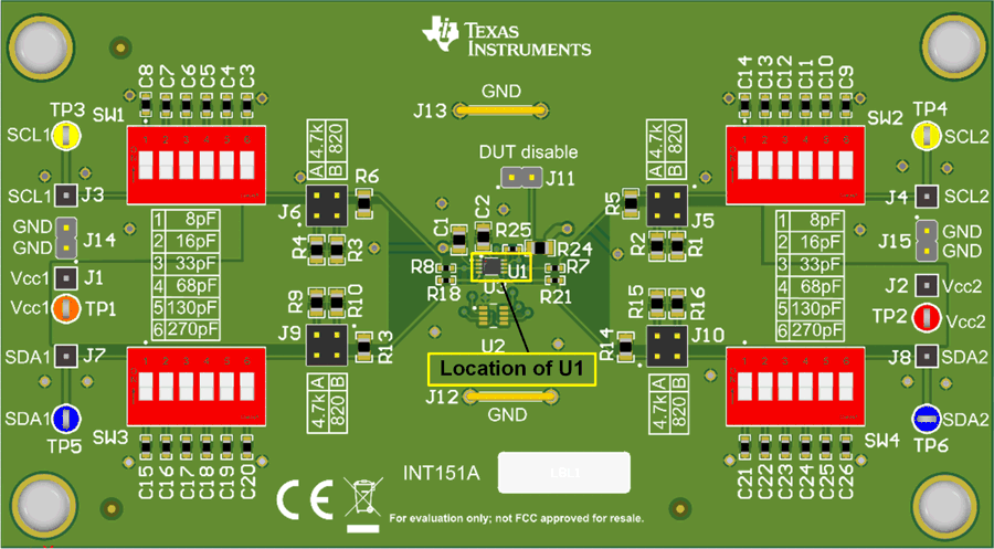
The TCA39306EVM comes populated with U1 as the DUT (Device Under Test) which is the TCA39306 in the DCU package seen in the Figure 2-3. The EVM includes the DDF package and the DTM package unpopulated.
 Figure 2-3 U1 location
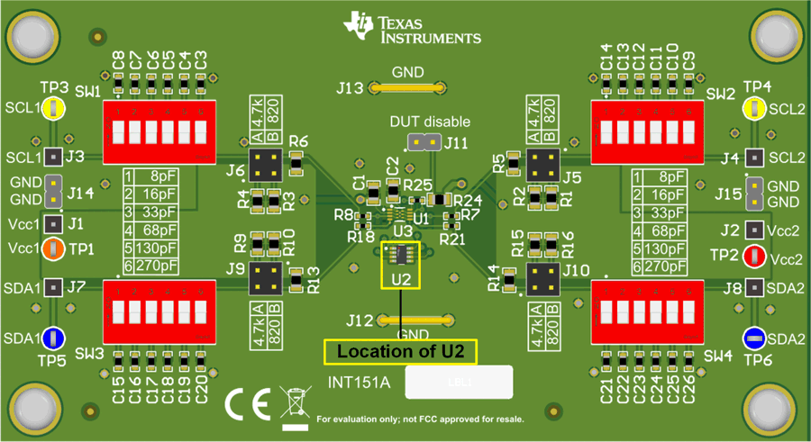
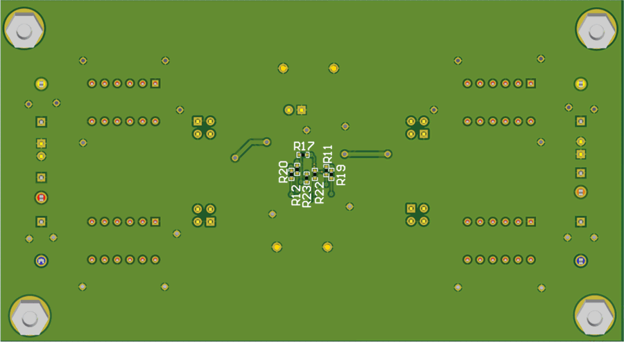
If the user would prefer to use the DDF package, then U1 would need to be removed and U2 can then be populated. In additional to populating U2, the resistors: R11, R12, R17, R19, R22, R20, and R23 all must be populated with 0 Ω resistors. These resistors can be found on the back of the EVM and shown in Figure 2-4.
 Figure 2-4 U2 populated
 Figure 2-5 Resistors on back of board
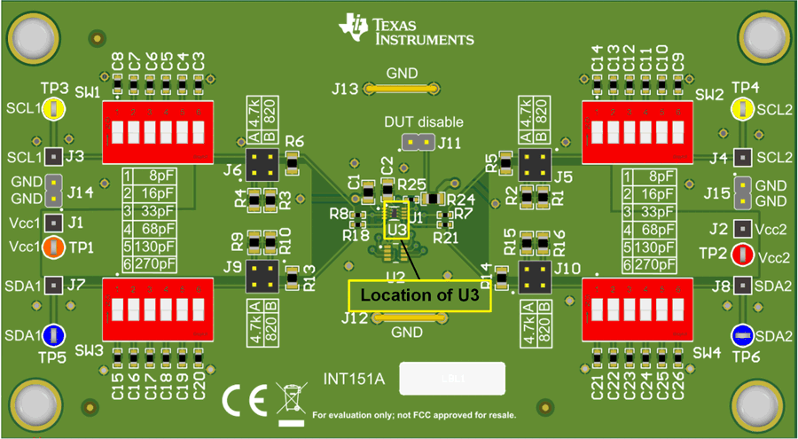
If the DTM package is required to be populated, U1 must be unpopulated to reveal the location of U3. Figure 2-6 shows the location of U3.
 Figure 2-6 U3 Location