SCPU045 June 2021
2.3 Load Capacitance Selector
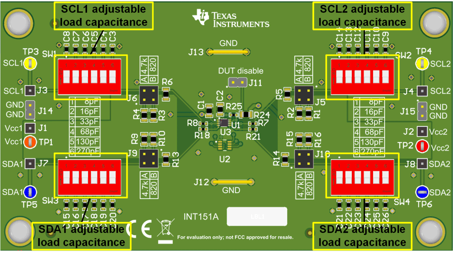
Figure 2-2 shows the board with the load capacitance selectors labeled.
 Figure 2-2 Load capacitor
selector
Figure 2-2 Load capacitor
selectorThe TCA39306 EVM provides a way for the designer to test the device under capacitive loading which is one of the main constraints in an I2C system. Switches denoted as S1, S2, S3, and S4 provide the user with the ability to change the I2C bus capacitance with up to about 525 pF of capacitance. The switched capacitor can be selected in increments of approximately 8 pF, 1 6pF, 33 pF, 68 pF, 130 pF, and 270 pF. For example: if the designer wants a total capacitance of 275 pF, the designer chooses to switch in 130 pF, 68 pF, 33 pF, 16 pF, and 8 pF for a combined capacitance of approximately 255 pF, device capacitance and PCB capacitance can be estimated to be about 20 pF resulting in approximately 275 pF.
Note that there is additional capacitance due to parasitics from the PCB line traces and ICs on the board. For SDA and SCL pins of a device, assume 10 pF maximum per device on the I2C line. One important aspect to remember is the TCA39306 device does not redrive an I2C signal. This means the capacitance on both sides of the device are not separated but are technically connected (meaning they add up in parallel) when the signal goes from LOW to HIGH from either SDA or SCL. This is highlighted because the I2C standard limits the bus capacitance to 400 pF for standard and fast mode and 550 pF for fast mode plus. If the I2C system is expected to exceed this amount, an I2C buffer and redriver will be necessary to separate the capacitance between the two sides to be below the required capacitance limits.
Current I3C specifications state bus capacitance loading should be less than 50 pF, so all switches should be turned to the off position when testing with I3C.