SLAA833A May   2018  – October 2019 MSP430FR2353 , MSP430FR2355


  1.   How to Use the Smart Analog Combo in MSP430™ MCUs
    1.     Trademarks
    2. 1 Introduction
      1. 1.1 Smart Analog Combo (SAC) Concept
      2. 1.2 Single-Supply Amplifier Design Consideration
      3. 1.3 Smart Analog Combo Driver Library
    3. 2 Smart Analog Combo Operation Modes
      1. 2.1 General Purpose Mode
        1.       Example 1. Code Example for Smart Analog Combo General-Purpose Mode
      2. 2.2 Buffer Mode
        1.       Example 2. Code Example for Smart Analog Combo Buffer Mode
      3. 2.3 Noninverting PGA Mode
        1.       Example 3. Code Example for Smart Analog Combo Noninverting PGA Mode
      4. 2.4 Inverting PGA Mode
        1.       Example 4. Code Example for Smart Analog Combo Inverting PGA Mode
      5. 2.5 DAC Mode
        1.       Example 5. Code Example for Smart Analog Combo DAC Mode
    4. 3 Smart Analog Combo Interconnection Configuration
      1. 3.1 Smart Analog Combo Cascading
      2. 3.2 Smart Analog Combo Interconnection With Other Peripherals
    5. 4 Smart Analog Combo Use Cases in Sensing Applications
      1. 4.1 Use Smart Analog Combo in Smoke Detector
      2. 4.2 Use Smart Analog Combo in Current Loop
    6. 5 References
  2.   Revision History

Buffer Mode

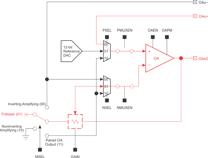
Figure 5 shows the SAC buffer mode. The buffer is unity gain, and it is also called a voltage follower. A voltage follower is often used to solve impedance matching problems, improve output drive strength, and isolate high-precision circuits from high-power circuits.

As the red highlighted part in Figure 5 shows, the signal input is from the positive port, the external pad, or the OA in SAC buffer mode. The output of the OA is isolated from the R-ladder, and PGA MSEL is set to floating status. The OA can output to an external pin or internally to a paired OA. To configure the SAC into buffer mode, the NSEL bits must select PGA source as negative input (NSEL = 01b), and MSEL bits must select buffer mode (MSEL = 01b). Example 2 shows one code sequence of configuring the SAC into buffer mode with driver library API functions.
SLAU445_SAC_BF.gifFigure 5. Smart Analog Combo Buffer Mode