SLAA833A May 2018 – October 2019 MSP430FR2353 , MSP430FR2355
- How to Use the Smart Analog Combo in MSP430™ MCUs
- Revision History
1.2 Single-Supply Amplifier Design Consideration
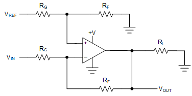
Because the Smart Analog Combo (SAC) is one of the analog peripherals in the MSP430 MCU, the SAC is supplied by the power pin on the MSP430 MCU. The integrated OA is a single-supply design with a wide supply voltage range from 2 V to 3.6 V. The OA inputs are referenced to ground. A dual-supply OA circuit design is straightforward, because the OA inputs and output are referenced to the normally grounded center of the supplies. The single-supply OA design is a little more complicated than a dual-supply OA as some form of biasing is usually required for single-supply OA. The OA input and output voltages must be within its two power rails. The SAC does not support negative voltage input or output. When the SAC is in inverting amplifier mode, biasing on the positive input is essential to avoid clipping distortion. Figure 2 shows the typical circuit for single-supply amplifier working in inverting mode. VREF and the resistor divider are used to generate bias voltage, and the SAC DAC12 with built-in reference can replace the external reference and resistor divider. With the SAC feedback resistance ladder, the circuit in Figure 2 can be implemented using one SAC without any external components.
 Figure 2. Single-Supply Inverting Amplifier
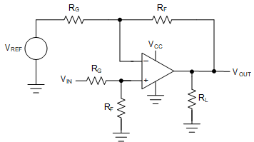
 When the SAC is in noninverting amplifier mode, if the DC component of input signal is small, it is acceptable to amplify both the DC component and AC component. If the input signal contains relatively high DC component while its AC component is small, amplifying the small AC component need high gain but amplifying the DC component with high gain leads to amplifier distortion. Adding biasing on the negative voltage input can address this issue by reducing the common-mode input voltage. Figure 3 shows the typical circuit for single-supply amplifier working in noninverting mode. Similar to the inverting amplifier circuit, the noninverting amplifier can also be implemented using the SAC without external components. The difference is that two SAC modules are needed, because the DAC can be connected only to the positive input of the OA, and the second SAC works in DAC mode to generate the bias voltage to the negative input of the OA. For more details and design considerations for single-supply amplifiers, see the Single-Supply Op Amp Design Techniques application report.
 Figure 3. Single-Supply Noninverting Amplifier