SLAAEE6 October   2023 MSPM0L1306 , MSPM0L1306


  1.   1
  2.   Abstract
  3.   Trademarks
  4. 1Introduction
  5. 2Hardware Introduction
  6. 3Software Introduction
  7. 4Gauge GUI Introduction
  8. 5Current Detection and Calibration Method
    1. 5.1 MSPM0 OPA Introduction
      1. 5.1.1 OPA input and output limitation
      2. 5.1.2 OPA Accuracy Influence
    2. 5.2 Current Detection Method
    3. 5.3 Current Calibration Method
      1. 5.3.1 (R1+R2)/R2 calibration
      2. 5.3.2 OPA1 Voffset calibration
      3. 5.3.3 R3/(R4+R3) calibration
      4. 5.3.4 Vref calibration
  9. 6Solution Evaluation Steps
    1. 6.1 Step1: Hardware Preparation
    2. 6.2 Step2: Evaluation
  10. 7MSPM0 Gauge Solution Test Results
    1. 7.1 Calibration Test Result
    2. 7.2 Current Detection Result
      1. 7.2.1 Test Under 25°C
      2. 7.2.2 Test Under 0°C
      3. 7.2.3 Test Under 50°C
      4. 7.2.4 Conclusion
    3. 7.3 Current Consumption Test
  11. 8Solution Summery and Improvement Direction
    1. 8.1 Shunter Resistor
    2. 8.2 ADC and its Reference
    3. 8.3 Runtime Calibration

Current Consumption Test

Figure 7-10 shows the current test result, under NO_OUTPUT mode, and after removing the tantalum capacitor, the temperature sensor, and voltage divider resistors. You just want to show the MCU power consumption of detection part. If customer wants to reach the same performance with full hardware setup, use the MOSFET or bipolar to control the voltage supply to resistor dividers.
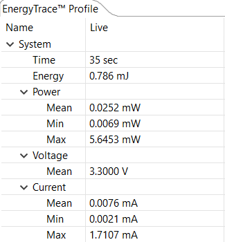
GUID-A32AD7CE-A3F4-46D6-823B-A06B62871A54-low.png Figure 7-10 Current Consumption