SLAAEF6 September   2023 MSPM0L1105 , MSPM0L1106 , MSPM0L1306 , MSPM0L1344 , MSPM0L1345 , MSPM0L1346


  1.   1
  2.   Abstract
  3.   Trademarks
  4. 1PIR Design Description
    1. 1.1 PIR Sensor
    2. 1.2 PIR Signal Chain
      1. 1.2.1 Traditional Motion Detection Signal Chain Design
      2. 1.2.2 Capacitor-Free Signal Chain Design
  5. 2Hardware and Schematic
    1. 2.1 MSPM0L1306
    2. 2.2 MSPM0 PIR Boosterpack
      1. 2.2.1 Schematic
  6. 3Software
    1. 3.1 Software Architecture
    2. 3.2 Software Flow Chart
    3. 3.3 Data Processing
      1. 3.3.1 Digital Signal Conditioning
      2. 3.3.2 Low-Pass Filter for Temperature Drift
      3. 3.3.3 Spikes and Noise
      4. 3.3.4 Motion Detection Function
  7. 4Results
    1. 4.1 Power Profile and Current Consumption
    2. 4.2 Detection Performance
      1. 4.2.1 Distance: 5 meters (16.4 ft)
      2. 4.2.2 Distance: 9 meters (29.5 ft)
      3. 4.2.3 Distance: 10 meters (32.8 ft)
  8. 5Summary
  9. 6References

Detection Performance

In order to test the range of the MSPM0 PIR motion detector, the device was positioned at the end of a hallway on a tripod. An adult would walk side-to-side at set distances at approximately 1 m/s, and the resulting absolute value of the signal would be analyzed. The threshold for the digital output code to detect motion was set to 30. The motion detector could reliably detect motion at the beginning 5 m range, and could detect with less sensitivity out to 9 m under the set test conditions. These result could be further optimized with further software development and possibly the use of different PIR lenses.
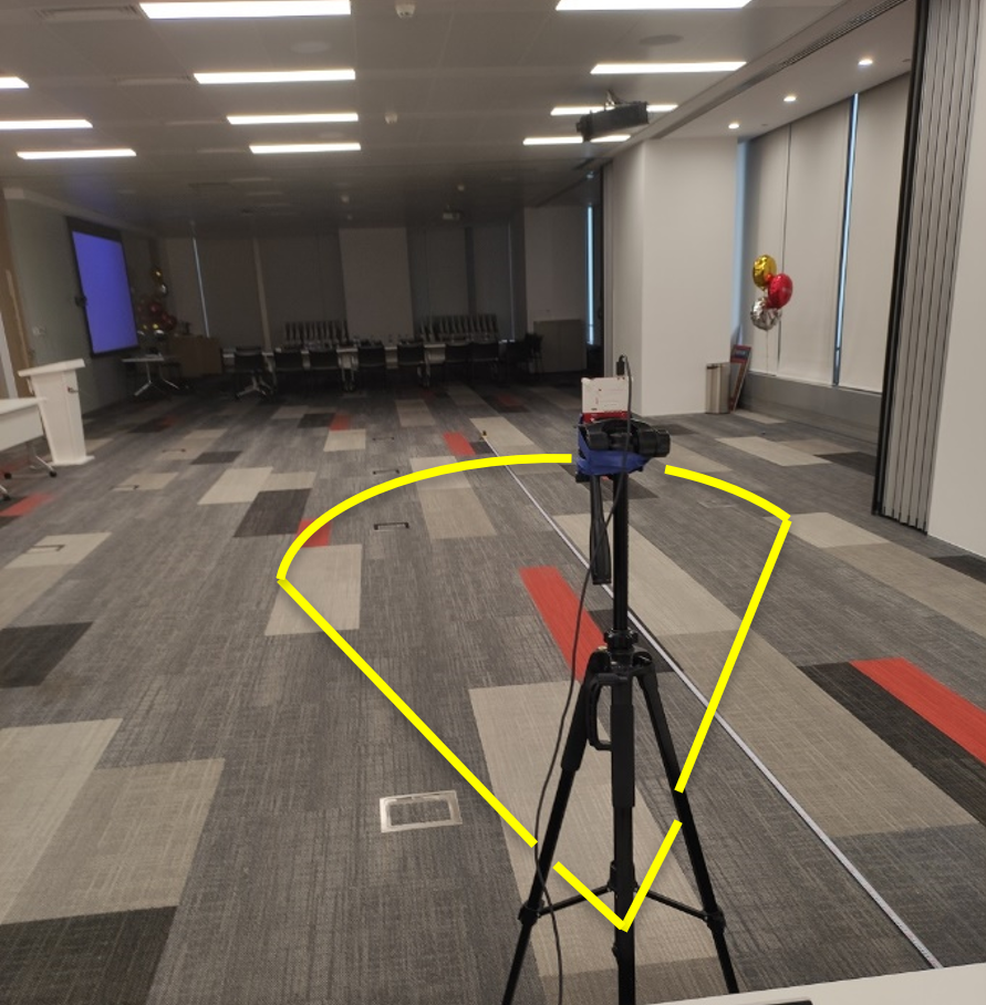
GUID-6BAB118A-2A5B-464C-BC61-3232E53CCECA-low.png Figure 4-2 MSPM0 PIR Motion Test Setup Example