SLAU904A October 2023 – December 2023
- 1
- Description
- Get Started
- Features
- Applications
- 6
- 1Evaluation Module Overview
- 2Hardware
- 3Software
- 4Hardware Design Files
- 5Additional Information
- 6References
- 7Revision History
2.3.1 TAx5x42 EVM Input Hardware Settings
The TAx5x42 evaluation module has several input configuration options and offers extensive flexibility to allow the user to evaluate the device across multiple operation modes. The different operation modes are highlighted in this section.
 Figure 2-8 TAC5242/TAC5142/TAA5242 EVM Input Architecture for Channel 1 and 2
The IN1 and IN2 input architecture allows these two channels to be quickly configured to support any of the supported operation modes. The INxP and INxM pins of the TAx5x42 can optionally connect to onboard microphones for quick evaluation of a microphone in AC- or DC-coupled modes. Jumper configuration details can be found in Table 3-2.
For TAD5242 or TAD5142, IN1 and IN2 components are not populated.
| Input Terminal | Input Mode | Installed Jumpers | Uninstalled Jumper | Input Swing | Topology |
|---|---|---|---|---|---|
| IN1 | LINE-IN Differential, AC-coupled | J8 | J4, J5, J6, J11, J12, J15, J16, J20, J21 | 2 VRMS | 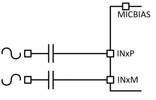 |
| LINE-IN Single-ended, AC-coupled | J6, J8, J12 (2-3) | J4, J5, J11, J15, J16, J20, J21 | 1 VRMS | 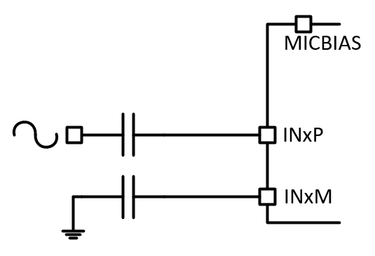 |
|
| LINE-IN Differential, DC-coupled | J15, J16 | J4, J5, J6, J11, J12, J20, J21, J8 (DUT MICBIAS is not used) | 2 VRMS | 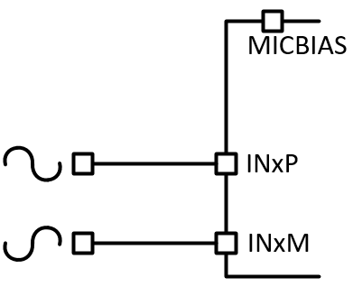 |
|
| LINE-IN Single-ended, DC-coupled | J6, J12 (2-3), J15, J16 | J4, J5, J11, J20, J21, J8 (DUT MICBIAS is not used) | 1 VRMS | 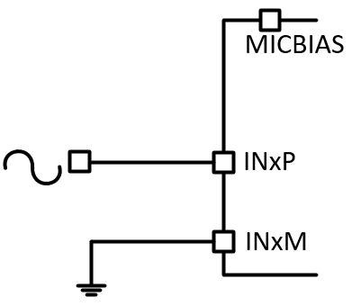 |
|
| On-board Electret Condenser Microphone (ECM) Differential, AC-coupled | J4, J5, J8, J11, J12 (1-2) | J6, J15, J16, J20, J21 | Refer to Microphone data sheet | 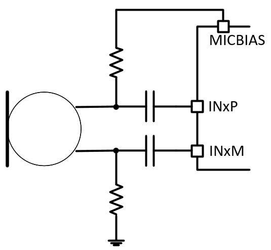 |
|
| On-board Electret Condenser Microphone (ECM) Single-ended, AC-coupled | J4, J5, J8, J11, J12 (2-3) | J6, J15, J16, J20, J21 | Refer to Microphone data sheet | 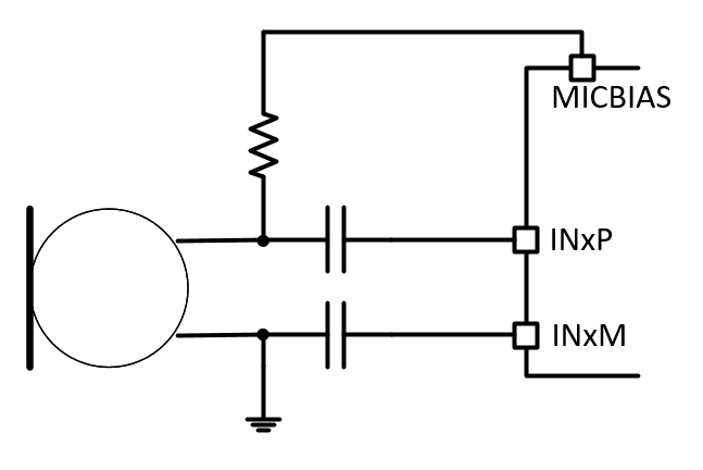 |
|
| On-board Electret Condenser Microphone (ECM) Differential, DC-coupled | J4, J5, J8, J11, J12 (1-2), J15, J16 | J6, J20, J21 | Refer to Microphone data sheet | 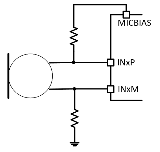 |
|
| On-board Electret Condenser Microphone (ECM) Single-ended, DC-coupled | J4, J5, J8, J11, J12 (2-3), J15, J16 | J6, J20, J21 | Refer to Microphone data sheet | 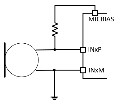 |
|
| IN2 | LINE-IN Differential, AC-coupled | J8 | J7, J9, J13, J14, J17, J18, J22, J23, J46 | 2 VRMS | |
| LINE-IN Single-ended, AC-coupled | J7, J8, J14 (2-3) | J9, J13, J17, J18, J22, J23, J46 |
1 VRMS |
|
|
| LINE-IN Differential, DC-coupled | J17, J18 | J7, J9, J13, J14, J22, J23, J46, J8 (DUT MICBIAS is not used) | 2 VRMS | |
|
| LINE-IN Single-ended, DC-coupled | J7, J14 (2-3), J17, J18 | J9, J13, J22, J23, J46, J8 (DUT MICBIAS is not used) | 1 VRMS | |
|
| On-board Analog MEMS microphone, AC-coupled | J8, J9, J46 | J7, J13, J14, J17, J18, J22, J23 | Refer to Microphone data sheet | 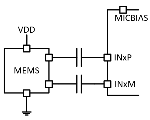 |
|
| On-board Analog MEMS microphone, DC-coupled | J9, J17, J18, J46 | J7, J13, J14, J22, J23, J8 (DUT MICBIAS is not used) | Refer to Microphone data sheet | 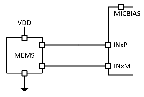 |