SLDU028A January 2018 – March 2020 TPS65313-Q1
-
TPS65313-EVM User’s Guide
- Trademarks
- 1 TPS65313-EVM Top View With Basic External Connections
- 2 TPS65313-EVM Input, Output Voltages, and Load Current Requirements
- 3 TPS65313-EVM Jumper Settings
- 4 TPS65313-EVM GUI Installing and Opening the GUI
- 5 TPS65313-EVM Power-Up and Power-Down Procedure
- 6 TPS65313 GUI
- 7 TPS65313-EVM Typical Plots
- 8 TPS65313-EVM Schematic Diagram
- 9 TPS65313-EVM Part List
- 10 PCB Layer Diagram
- 11 Description of the Watchdog Algorithm Implemented on EVM
- Revision History
6.3 EEPROM Programming Page
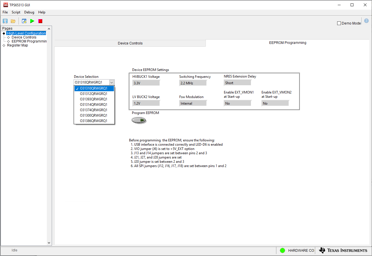
The TPS65313-Q1 device has many factory programmable device options with unique orderable part numbers. By default, the TPS65313-EVM has a device with the O31310QRWGRQ1 orderable part number. If users want to evaluate different device options (or orderable part numbers), the EEPROM configuration can be updated using this page as shown in Figure 7. Not all the device options samples are readily available or it may be possible to have a device configuration which is not listed here. Contact TI local sales team for sample availability and feasibility.
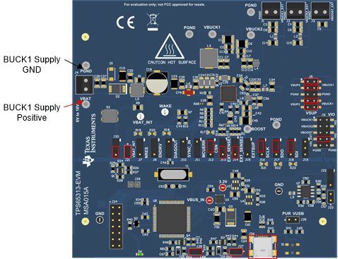
Keep the VBAT supply voltage between 10 V and 18 V while updating the device options or orderable part number. All the jumpers should be set according to Figure 8. For a list of orderable part numbers, refer to the TPS65313-Q1 Wide-VIN Power-Management IC for Automotive Applications datasheet.To select an orderable part number in the GUI, click the Device Selection drop-down menu. Then click the Program EEPROM button. If the orderable part number is successfully updated, a message is displayed to power off and power on the device to make the changes effective. Once EEPROM Programming is completed successfully, bring the jumper settings back to its original settings specified in Table 2TPS65313-EVM Jumper Settings as in EEPROM Programming mode, device may get damaged if VBAT voltage is more than 18 V.
Device output voltages are accurately trimmed at the factory for the O31310QRWGRQ1 orderable part number only. Output voltage accuracy can be affected slightly for other device options generated using the GUI EEPROM programming method. However, if the user orders device samples according to the device options table in the data sheet, these devices will be correctly trimmed at the factory to have best output voltage accuracy.
 Figure 7. TPS65313 GUI EEPROM Programming Page
  Figure 8. Jumper Settings for EEPROM Update