SLIA096 January 2022 DRV5021 , DRV5021-Q1 , DRV5023 , DRV5023-Q1 , DRV5032 , DRV5033 , DRV5033-Q1 , TMAG5123 , TMAG5123-Q1 , TMAG5124 , TMAG5124-Q1 , TMAG5131-Q1 , TMAG5231 , TMAG5328
2.8.5 External Fields
External fields can raise or lower the threshold angles observed in this particular design depending on the magnet orientation. One particular field that is present in nearly unshielded designs is the earth's magnetic field. This field ranges with respect to location, displacement from the earth's surface, and Hall-element orientation with respect to the earth's surface. Nearby magnets and high current carrying wires such as in a motor are also examples of external field sources. In the test environment, linear output device was used to measure an external field 42.9 μT for the board location and orientation.
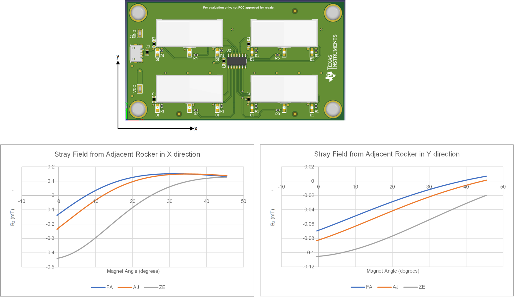
One other external or stray field that is inherent to the particular design, is the field from any other magnet in one of the adjacent rockers. Figure 2-32 illustrates how much external field might be expected from a nearby rocker. As it falls well below the lowest BOP minimum of 1.8 mT, this is not considered to be a significant issue in this design. However, if the rockers were spaced closer together, then it might become a significant issue for the DRV5033 devices. Shielding or using higher threshold devices should minimize this concern.
 Figure 2-32 Impact of Adjacent Rocker
Switches
Figure 2-32 Impact of Adjacent Rocker
SwitchesExternal fields should simply offset the magnetic field curve. As illustrated in Figure 2-33, an offset that lowers the curve tightens the switch region and lower the BOP angle as seen in region 1 while an offset that raises the curve leads to a wider transition region and a higher BRP angle as seen in region 3. As omnipolar switches were used, strict attention was not directed to which polarity faced the device in the assembly of these rocker switches. For less variation, consistently orienting a specific polarity toward the Hall-effect switch leads to more consistent results.