SLLA609 September 2023 ISOM8110 , ISOM8710 , ISOM8711
2 What are Optocouplers?
Optocouplers are isolation devices containing a light-emitting and light-sensitive component to transmit signals while blocking ground potential differences (GPDs) between the them. The light-emitting component is typically a light-emitting diode (LED) while the light-sensitive component is usually a phototransistor or photodiode.
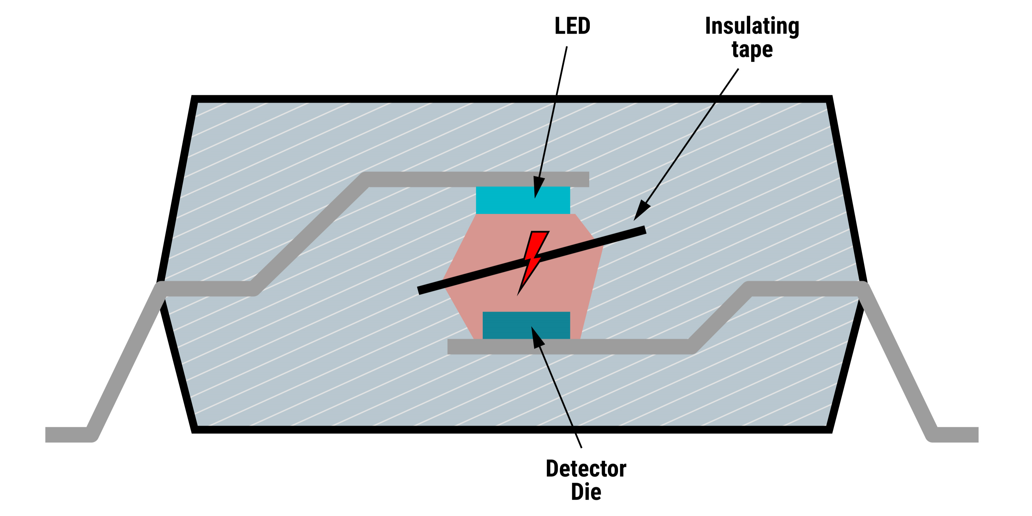
For an optocoupler to achieve signal isolation, the LED and phototransistor (or photodiode) inside are physically separated by distance and an insulated material. This insulated material can be an epoxy, mold compound, or just an air gap: all three of which have relatively low dielectric strength properties for voltage insulation. Figure 2-1 shows an illustrated cross section of an optocoupler:
 Figure 2-1 Optocoupler Cross-Section
With time, signal transmission through optocouplers is degraded by aging of the LED and clouding or yellowing of the semi-transparent isolation material used. As the LED dims or the epoxy yellows with age, strength of the transmitted light erodes; thus, more current is required to drive the LED input to the brightness achieved when the optocoupler was new. If the system designer does not compensate for this signal transmission degradation, the optocoupler's ability to transmit input signals to the isolated output can eventually reach a marginal point and even completely fail. To counter this, most optocouplers require a guardband of input current additional to the data sheet specifications be included in designs so that the LED can better transfer the signal across the lifetime. This additional input current results in higher and potentially unnecessary power consumption by the optocoupler and entire system starting from the very beginning of the design.
During normal operation, high slew rate or high frequency transients on either side of an isolated device can corrupt data transmission across the isolation barrier. Common mode transient immunity (CMTI) is the maximum tolerable rate of rise or fall of the common mode voltage applied between two isolated circuits. This is usually measured in dv/dt, and the unit is normally kV/µs or V/ns. CMTI is a critical signal integrity parameter that correlates to isolated signal robustness for all isolated signal devices which are subject to differential voltages between two separate ground references. With the increasing progress and adoption of new generation power semiconductor devices, customer end equipments and applications are requiring faster switching frequencies with higher magnitudes. Most high-speed digital optocouplers have CMTI specifications of 25 kV/µs maximum. This low of a CMTI maximum value allows for glitches in the output signals of digital optocouplers during fast common-mode transients between ground planes, such as during switching of transistors in power supply or inverter applications. For this reason, optocouplers are not typically used in applications requiring fast switching of high-density power applications.
Many popular optocouplers are known for their diode input and transistor output characteristics and are used such that the output transistor sinks a current proportional to that flowing through the input LED. The parameter quantifying this attribute is known as the current transfer ratio (CTR) and is defined as the ratio of output current (IC) through the transistor to input current (IF) of through the input LED expressed as percentage. With time and temperature, most optocoupler CTR values can vary dramatically. Similar to the case with LED aging, this means that to make sure the output drive strength is high enough for proper signal transmission, system designers must consider the worst-case variation and increase the input forward current accordingly. This also results in undesired, and possibly unnecessary, power dissipation through the optocoupler.