SLOU559 April 2023
8 GUI Operations DRV8845
Note: The MSP430 microcontroller used in DRV8845EVM
only has two onboard DACs. DAC0 provides microstepping reference voltages VREF1 and
VREF3 simultaneously and DAC1 provides microstepping reference voltages VREF2 and
VREF4 simultaneously. Because of this limitation while running both stepper motors
they will run with the same setting parameters. To run two stepper motors
simultaneously with independent control settings, remove the jumper shorts for the
required signal inputs and provide control inputs from an external source such as an
application microcontroller.
- Go to the “Driver Control” tab.
- Stepper Motor Control
- Select “Stepper Motor Control”.
- Set the “Motor Driver” to “Awake” and the required stepper driver outputs to “Enabled”
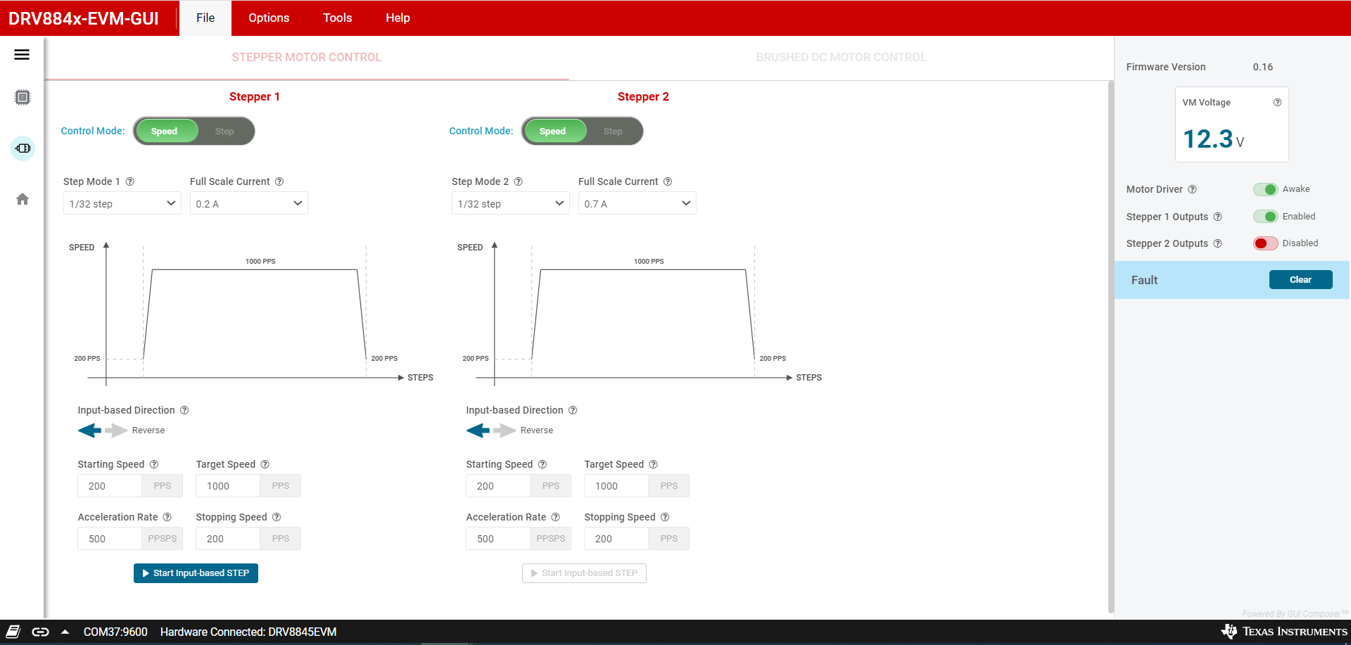
- Select the desired “Control Mode” – This is a GUI app feature which allows selection between “Speed” mode and “Step” mode. In speed mode the motor can run at the set target speed using the defined acceleration and deceleration rate motion profile. In “Step” mode the motor can be stepped to the desired position by setting the required number of steps at the set target speed.
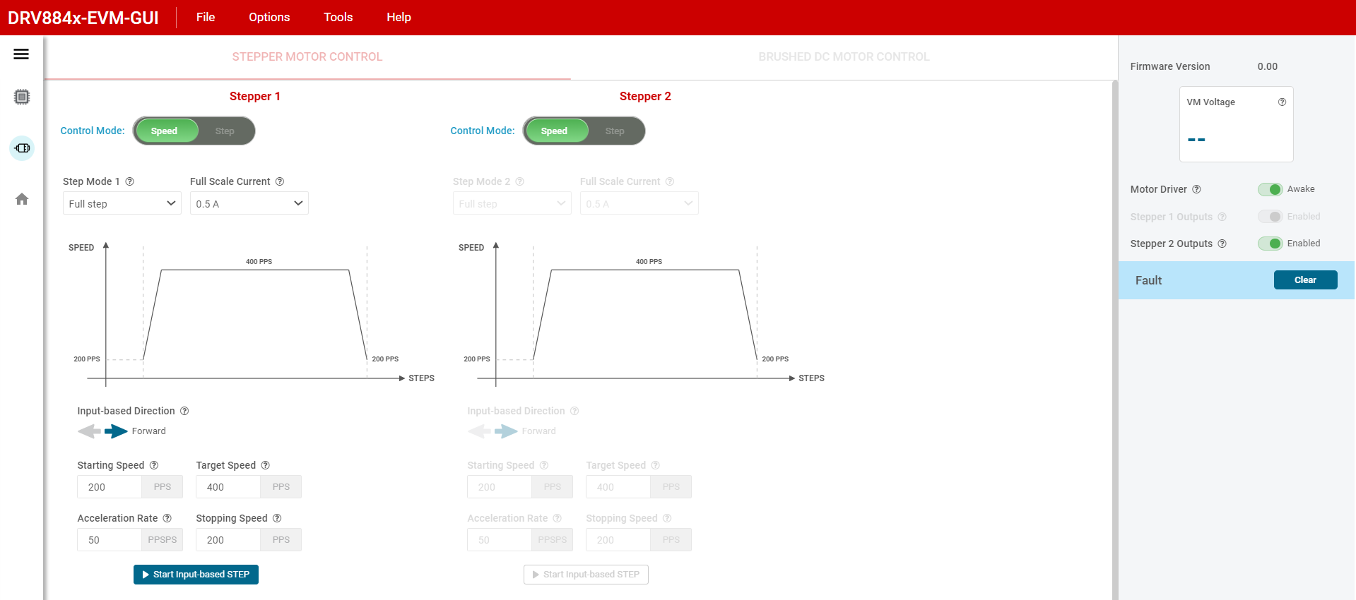
- Spinning Two Stepper
motors:
- Enable Stepper 1 Outputs, then Stepper 2 Outputs. Notice that Stepper 1 Outputs Enabled is greyed out and the Stepper 2 motor controls is greyed out.
- Now Stepper 1 Controls is used to control both motors.
- Please note that if you start by enabling Stepper 2 Outputs then you are not able to spin two motors.
- Features:
- Step Mode: Can be used to set the microstepping mode
- Full Scale Current: Can be used to set the full scale current value
- Starting Speed: The speed at which the motor starts spinning
- Target Speed: The final target speed of the motor
- Acceleration Rate: Set the acceleration rate at which the motor reaches the target speed
- Stopping Speed: Can be used to set the stopping speed of the motor
- Number of Steps: Sets the number of steps to cover
- Steps to Stop: Sets the number of steps to stop
- Fault Clear: used to clear driver faults.
- Adjust the settings as
needed and select “Start Input Based STEP” to start spinning the motor
and use the “Input-based Direction” to change motor direction.
 Figure 8-1 Stepper
Control in DRV8845-EVM-GUI
 Figure 8-2 Dual
Stepper Control in DRV8845-EVM-GUI
- Brushed Motor Control
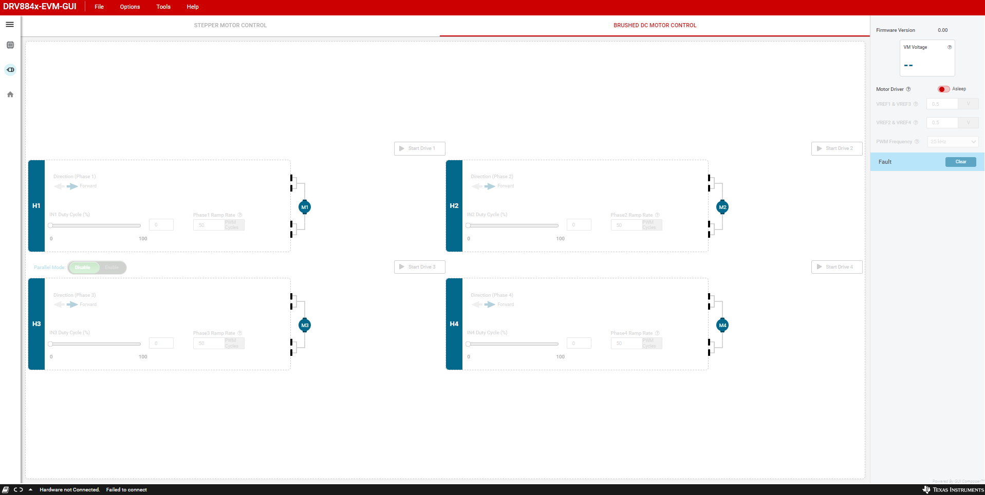
- To switch from “Stepper Motor Control” to “Brushed DC Motor Control”, first disable the stepper outputs and then put the motor driver to “Asleep” state.
- Set the “Motor Driver” to “Awake”
- Use the VREF1 & VREF3 and VREF3 & VREF4 widget inputs to enter a reference voltage less than or equal to 0.5625 V (0.5625 corresponds to 1.5 A based on the 330 milliohms current sense resistors used in the Rev A EVM hardware – see PWM Current Control section of the device data sheet).
- Use PWM Frequency drop down to select the desired PWM frequency.
- Select the desired number of Full bridges using the “Start Drive X” tab.
- Adjust the speed of the motor using the “Duty Cycle” slider.
- Adjust the direction of the motor spinning using the “Direction” tab
- The Phase x Ramp rate can be used to set the duty cycle ramp rate to the new set value.
- Parallel Mode:
- To enter parallel
mode:
- Put the device to sleep
- Turn off power supply (VM)
- Disconnect the USB from computer
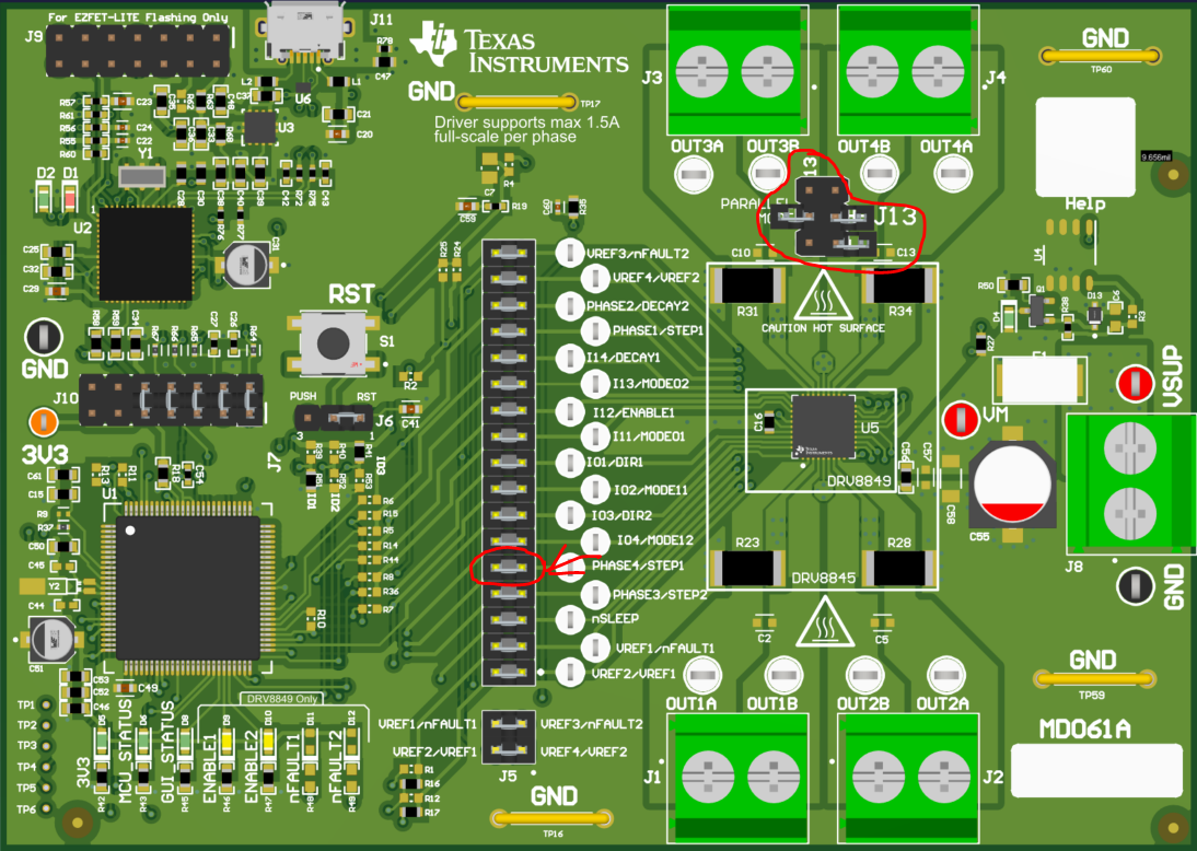
- Remove jumper on PHASE4/STEP1
- Populate all jumpers on connector J13
- Reconnect USB
- Turn on power supply (VM)
- Go to Brushed Motor Control
- Turn on Motor Driver (awake state)
- Enable the Parallel Mode. H3 becomes H3 and H4. Whereas the earlier H4 will be greyed out.
- Then connect the BDC motor to Phase 3 (Connecter J3)
- To exit parallel
mode:
- Disable the Parallel Mode
- Put Motor Driver to asleep state
- Turn off power supply
- Disconnect USB
- Remove jumpers on J13
- Repopulate jumper on Phase4/STEP1
- Reconnect USB
- Turn on power supply
- Put the motor Driver to Awake state
 Figure 8-3 Parallel Mode Jumpers
 Figure 8-4 Brushed DC Motor Control in
DRV8845-EVM-GUI
- To enter parallel
mode: