SLOU559 April 2023
2 Jumpers Table and Setup
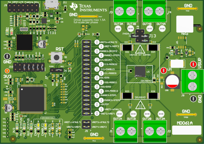
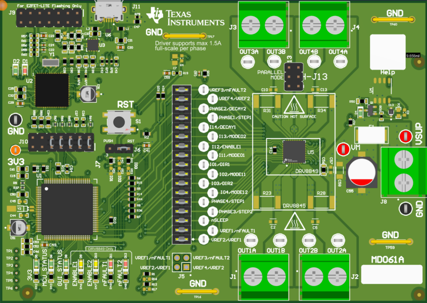
The jumpers for the DRV8845EVM Figure 2-1 and DRV8849EVM Figure 2-2 are identical except for J5 and J13 and the below figures can be referred to for proper connection.
 Figure 2-1 DRV8845EVM Jumper Population
Guide
 Figure 2-2 DRV8849EVM Jumper Population
Guide
Figure 2-2 DRV8849EVM Jumper Population
GuideTable 2-1 Jumper Identification Table
Jumpers | DRV8845EVM/DRV8849EVM |
|---|---|
| J1-J4 | OUT1A, OUT1B – OUT4A, OUT4B |
J5 | Connect VREF1 with VREF 3 and VREF2 with VREF4 for DRV8845EVM Leave unconnected for DRV8849EVM |
J6 | Push button to reset MCU |
J7 | MCU to DRV signals |
J8 | VM |
J10 | EZ FET communication jumpers |
J11 | Micro USB connection |
J13 | Jumpers for parallel drive |
Note that the labels for Jumpers J5 and J7 are separated with a “/” where the left label corresponds to DRV8845 and the right one corresponds to DRV8849.
For more detailed information download the hardware files and schematics. Once you have verified that all shunts and jumpers are in the correct location you can move on to hardware setup.