SLUA669B March 2013 – September 2023 UCC27511 , UCC27531 , UCC27532 , UCC27533 , UCC27536 , UCC27537 , UCC27538
2.4 Bootstrap Bias Supply with Isolated High/Low side Gate-Driver Solution
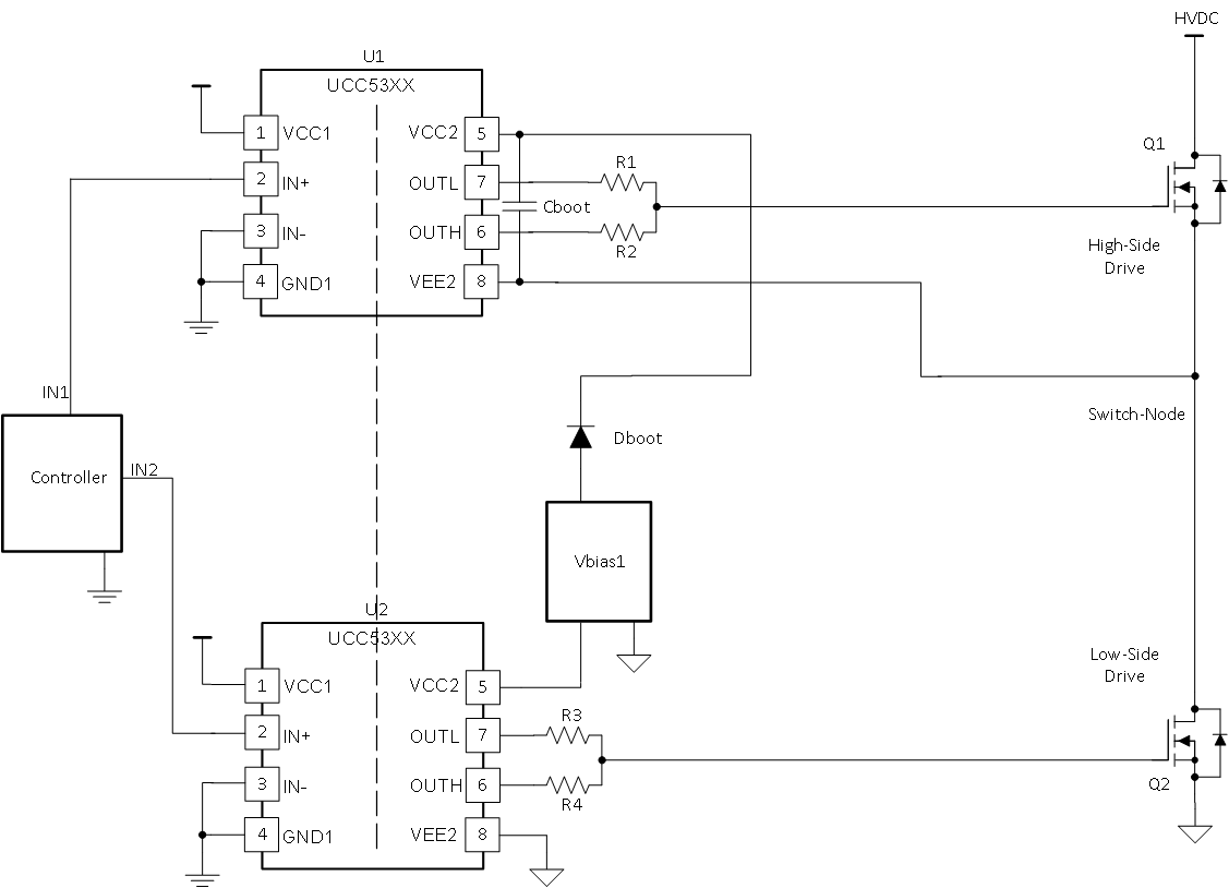
 Figure 2-4 Isolated Drivers Using High-Side Bootstrap Circuit
Signal Isolation
The input signals of U1 are isolated in Figure 2-4, with the isolated gate driver, UCC53xx. This allows the signal to operate properly, even as the signal reference (switch-node) changes voltage throughout the switching period. It also isolates the controller ground from the switch-node and power ground.
High-Side Bias
In Figure 2-4, Dboot and Cboot are used as a bootstrap circuit to bias U1 properly. In the UCC27712 datasheet, refer to for selecting Cboot and for selecting Dboot.