SLUAA80 November 2020 TPS40322
3.1 Connection Block Diagram
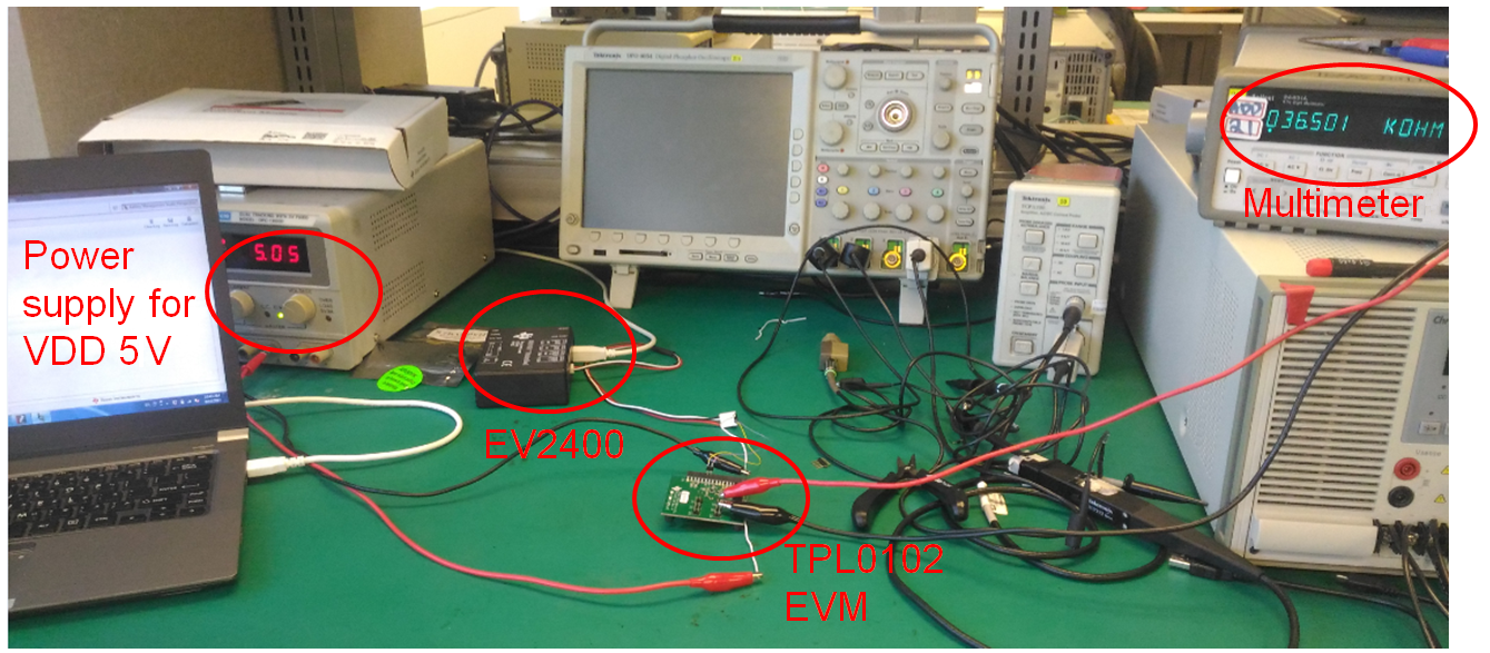
This section details the hardware equipment and setup.
Hardware Equipment:
- PC or laptop
- EV2400
- TPL0102 EVM
- DC power supply
Hardware Setup:
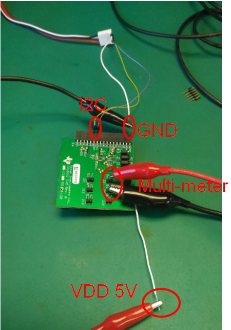
- Insert header caps in J1, J2, and J3 to set A2, A1, and A0, respectively. The board is shipped with the following settings: A2 = 0, A1 = 0, and A0 = 1.
- Connect the I2C bus of the host(EV2400) to the board via connector J14 (pins marked SCL, SDA). Also connect the GND pin on J14 to GND of the host processor.
- Apply the positive supply voltage 2.7 V–5.5 V(VDD) to center pin of J4. Apply GND to lowest pin of J4.
- Apply the negative supply voltage (VSS) to J5. The board is shipped with a header cap that connects VSS to GND.
- Write to the TPL0102 data registers per protocol in the TPL0102 Two 256-Taps Digital Potentiometers With Non-Volatile Memory Data Sheet.
- Measure resistance between H, W, L terminals as appropriate on headers J8–J13.
 Figure 3-1 Hardware Setup.
  Figure 3-2 TPL0102 EVM Board Connection.