SLUUCV8 October 2023 TPS4810-Q1
3.1.2 Overload and Short Circuit Protection Test
Use the following instructions to perform over current test on the TPS4810Q1EVM:
- Turn ON the power supply and set the power supply output VIN = 48 V, current limit = 50 A.
- Set the Short Circuit Protection (SCP) threshold at 30 A by installing jumper J3 in 3-4 position and install jumper J2 in 1-2 position to set 1-ms delay.
- Enable the control inputs (INP1 and INP2).
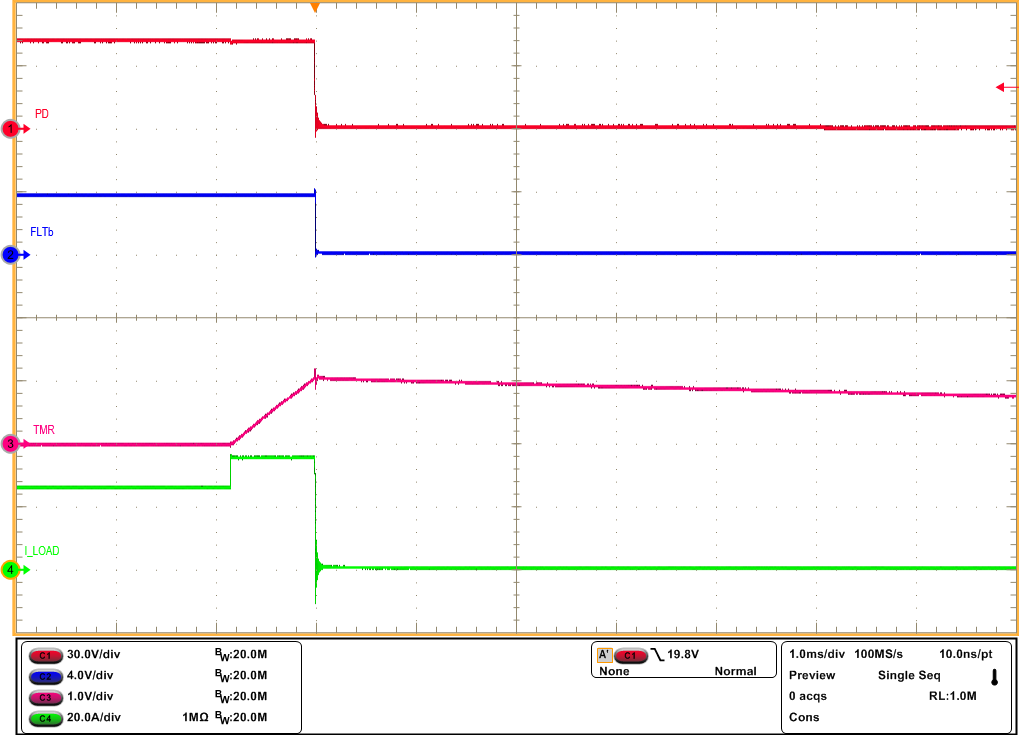
- Now, load the output to 25 A with electronic load and apply a step of 10 A to observe the overload behavior of TPS48100-Q1.
- Disconnect the load.
- To perform short-circuit test, uninstall J2 to set shortest SCP delay.
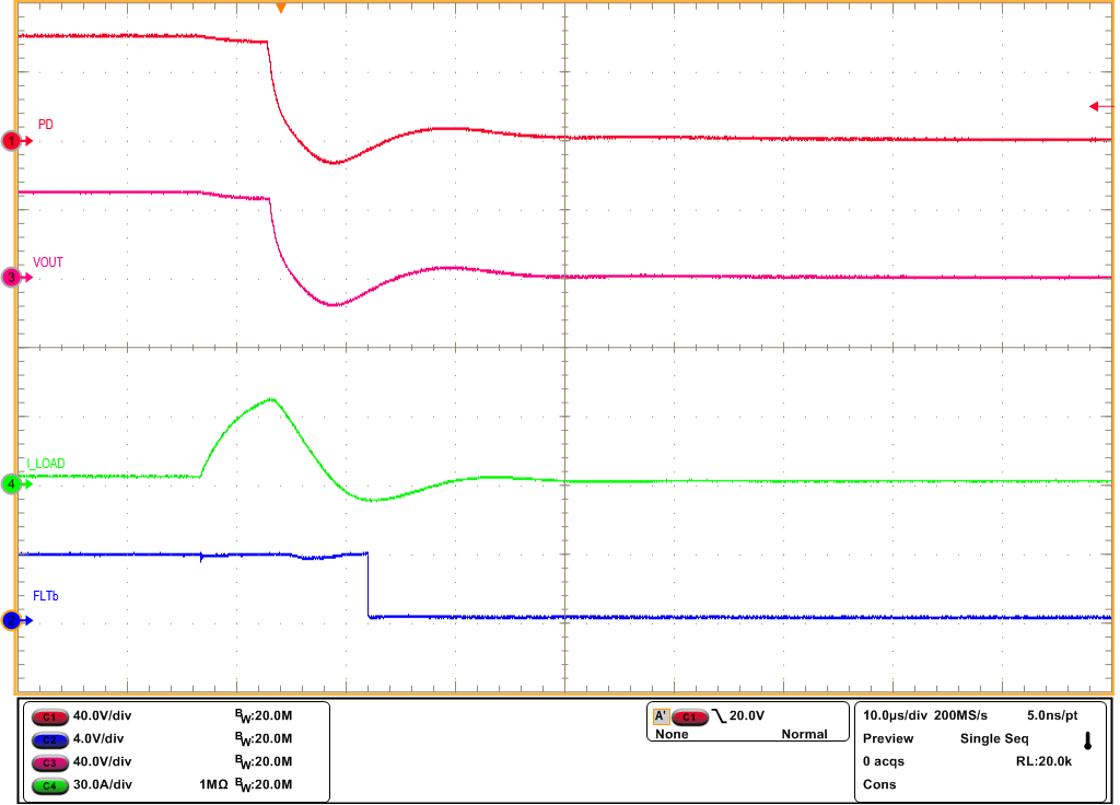
- Perform output short to capture the short-circuit behavior of TPS48100-Q1.
 Figure 3-4 Overcurrent Response of TPS4810Q1EVM for 25-A to 35-A Load Step
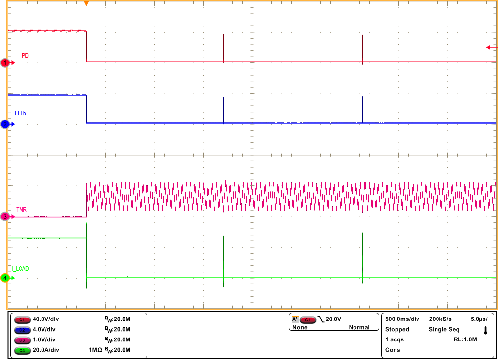
 Figure 3-5 Auto-Retry Response of TPS48100-Q1 for an Overcurrent Fault
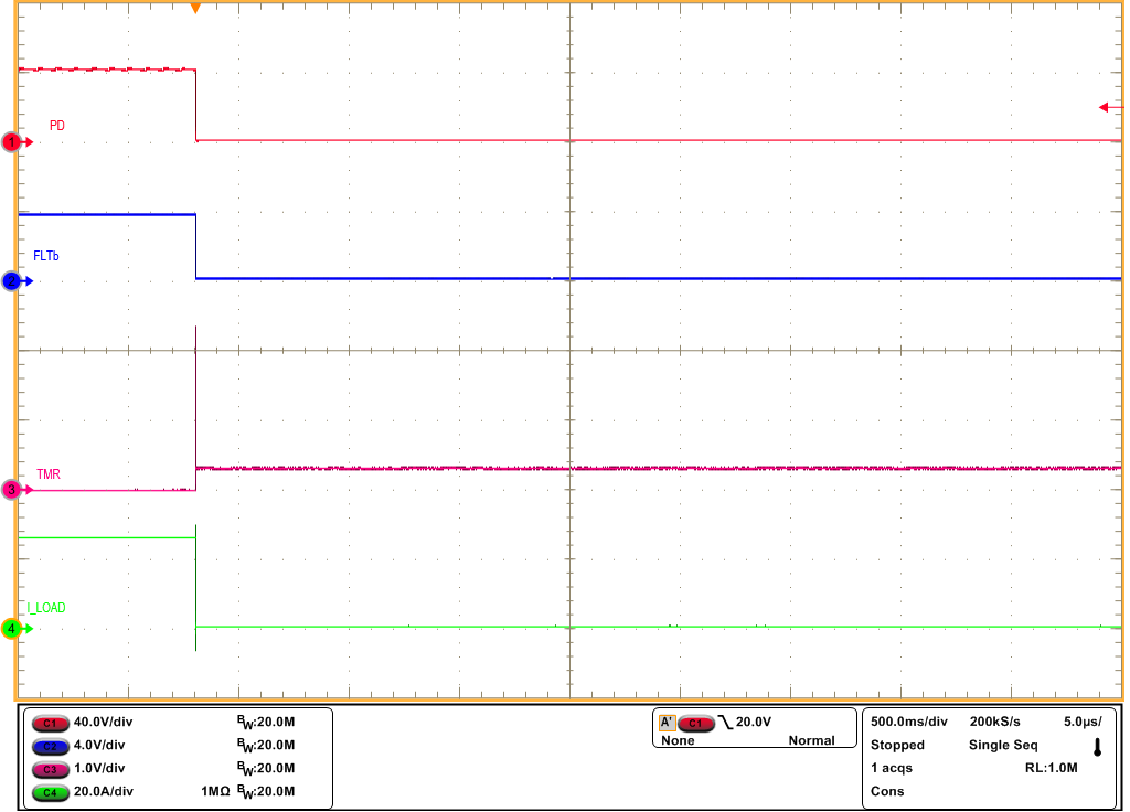
 Figure 3-6 Latch-off Response of
TPS48100-Q1 for an Overcurrent Fault
 Figure 3-7 Output Short-Circuit Response
of TPS48100-Q1