SLVAE11A August 2018 – January 2021 TPS65987D , TPS65988
4.1 Barrel Jack Connect Event PD Flow
Actual PD trace of this example Barrel Jack Event implementation in a system is shown in this section. This event can be used in a docking application when external power becomes available to the docking station. Rising edge on the GPIO that has been assigned for Barrel Jack Event initiates the required PD message flow for power role swap.
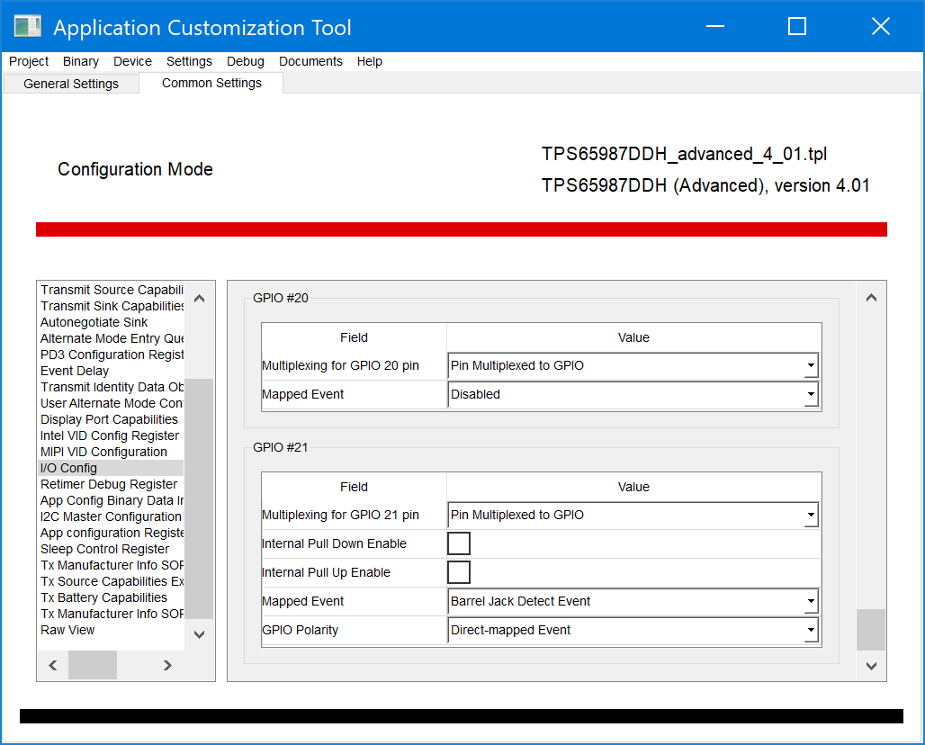
Two TPS65987D EVMs loaded with a binary created from the example template by clicking Project→TPS65987DDH→Advanced→Dual Role Port (DRP), prefers data host→None (DisplayPort Only) and GPIO21 is set to Barrel Jack Detect Event as shown in Figure 4-1.
 Figure 4-1 GPIO 21 Settings
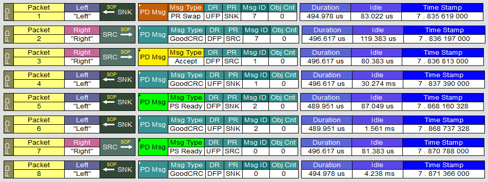
PD message trace is taken with a Teledyne LeCroy PD analyzer between two TPS65987D EVMs as shown in Figure 4-2.
 Figure 4-2 PD Trace of Barrel Jack Connect Event
Messages in Figure 4-2 represent PD traffic flow once the Barrel Jack adapter supplying 20 V is connected to the EVM-DCK configured with settings appropriate for a docking station.
Packet 1 → EVM-DCK is UFP/SNK and sends “PR Swap” message to the EVM-LPT which is DFP/SRC.
Packet 2 → DFP/SRC sends “GoodCRC” acknowledgment response for “PR Swap” message.
Packet 3 → DFP/SRC sends “Accept” message to signal that it is willing to do a Power Role Swap and has begun the Power Role Swap sequence.
Packet 4 → UFP/SNK sends “GoodCRC” acknowledgment response.
Packet 5 → EVM-LPT changes role to DFP/SNK and sends “PS Ready” message. It is important to note that the initial Source Port is now setting the “Port Power Role” field to Sink in the “PS Ready” message indicating that the initial Source’s power supply is turned off.
Packet 6 → EVM-DCK sends “GoodCRC” acknowledgment response for “PS Ready” message. Note that the GoodCRC Message sent by the initial Sink in response to the “PS Ready” message from the initial Source will have its Port Power Role field set to Sink since this is initiated by the Protocol Layer.
Packet 7 → EVM-DCK changes role to UFP/SRC and sends “PS Ready” message.
Packet 8 → EVM-LPT which is now DFP/SNK sends “GoodCRC” acknowledgment response.