SLVAE32B August 2018 – December 2023 TPS7H2201-SP
- 1
- Abstract
- Trademarks
- 1 Device Overview
- 2 Single-Event Effects
- 3 Test Device and Evaluation Board Information
- 4 Depth, Range, and LETEFF Calculation
- 5 Irradiation Facility and Setup
- 6 Test Setup and Procedures
- 7 Single-Event-Latchup (SEL), Single-Event-Burnout (SEB), and Single-Event-Gate-Rupture (SEGR)
- 8 Single Event Transient (SET)
- 9 Total Ionizing Dose From SEE Experiments
- 10Orbital Environment Estimations
- 11Confidence Interval Calculations
- 12Summary
- 13References
- 14Revision History
6 Test Setup and Procedures
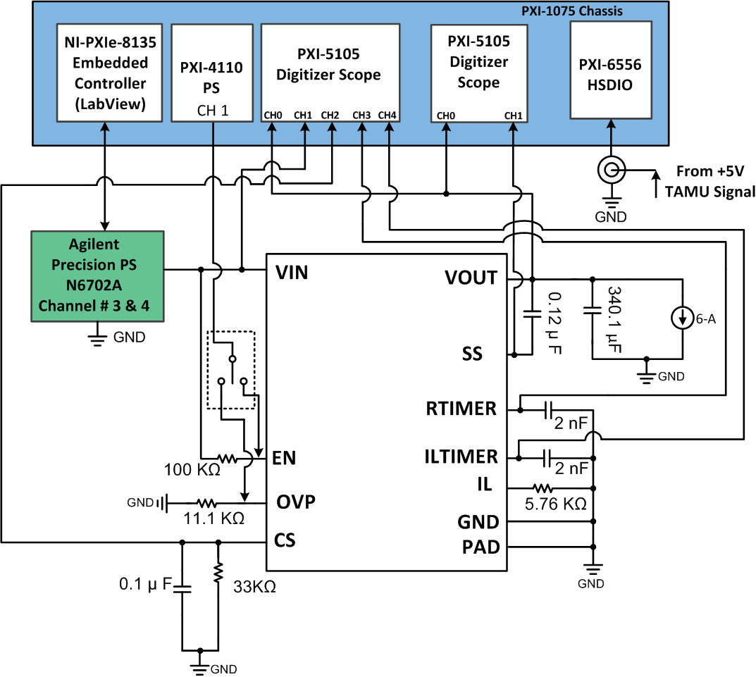
SEE testing was performed on a TPS7H2201-SP device mounted on a TPS7H2201EVM-CVAL. The device power was provided to the VIN-GND input on the J26 terminal block inputs using the N6702 precision power supply (PS) in a 4-wire configuration. For the SEL, SEB, and SEGR testing, the device was powered up at seven volts and loaded with approximately 1.1-Ω discrete resistors (six amps). The VOUT under this condition was 6.76 volts. For the SEB and SEGR characterization, the device was tested under enabled and disabled modes. An NI PXI-4110 PS was used to control the EN voltage to enable and disable the DUT. The discrete resistive load was connected even when the DUT was disabled to help differentiate events during testing. Not a single current increment event was observed during any of the SEL, SEB, and SEGR testing.
For the SET characterization, the device was powered up at minimum and maximum recommended voltages of 1.5 V and 7 V, and loaded to the maximum six amps using discrete resistors.
All equipment was controlled and monitored using a custom-developed LabVIEW® program (PXI-RadTest) running on a NI-PXIe-8135 controller. The current of the power supply, the temperature and the beam start and stop (5-V tamu signal) signal were monitored at all times and logged for further analysis.
Figure 6-1 shows a block diagram of the setup used for SEE testing of the TPS7H2201-SP. Table 6-1 shows the connections, limits, and compliance used on the test equipment. For the SEB/SEGR characterization, the die temperature was maintained between 20°C to 25°C by using a vortex tube to cool down the device when needed (when the part was enabled and loaded to 6-A). A die temperature of 125°C was used for SEL testing and was achieved by attaching three parallel power resistors (model: RP60800R0100JNBK) to the thermal pad on the back of the board using solder paste. The die temperature was monitored during the testing using a K-Type thermocouple attached to the heat slug of the package, and correlated using a thermal camera before the SEE characterization. As observed on Figure 6-1, two scope cards were used to trigger from VOUT and SS in case of a transient. The scope card triggering from VOUT was also monitoring VIN, CS, RTIMER, and ILTimer. The trigger used was a window set at ±3 % around the nominal output voltage (when the device was enabled) and ±200 mV (when the device was disabled). The scope card was set with a sample rate of 5 MS / s , record length of 60 kS per record and reference of 20%. A reference of 20% means that in case a trigger occurs, the 20% (12 kS) of the data before the time the trigger occurred was saved. For the scope card, triggering from SS the VOUT was also monitored. The trigger type used for SS was a edge positive trigger set at 500 mV. The scope card was set 2 MS / s, record length of 60 kS per record and 20% reference. Both scope cards were continuously monitoring the trigger signals and data was saved only if this signal exceeded the trigger set on the scope card.
All boards used for SEE testing were fully checked for functionality and dry runs were performed to make sure that the test system was stable under all bias and load conditions prior to being taken to the TAMU facility. During the heavy-ion testing, the LabView control program (PXI-RadTest) powered up the TPS7H2201-SP device and set the external sourcing and monitoring functions of the external equipment. After functionality and stability were confirmed, the beam shutter was opened to expose the device to the heavy-ion beam. The shutter remained open until the target fluence was achieved (determined by external detectors and counters).
| Pin Name | Equipment Used | Capability | Compliance | Range of Values Used |
|---|---|---|---|---|
| VIN | Agilent N6702A (Channels 2 and 3 in parallel) | 10 A | 10-A | 1.5 and 7 V |
| EN | ni-PXIe-4110 (Channel 1) | 1 A | 0.1-A | 0 and 1 V |
| Digital I/O | NI PXIe 6556 | 200 MHz | — | 50 MHz |
| Vout | NI PXIe 5105 | 60 MHz | — | 5 MHz |
| SS | NI PXIe 5105 | 60 MHz | — | 2 MHz |
 Figure 6-1 Block Diagram of SEE Test
Setup Used for the TPS7H2201-SP Characterization
Figure 6-1 Block Diagram of SEE Test
Setup Used for the TPS7H2201-SP CharacterizationThe single pole, double throw (SPDT) switch shown on the EN pin was not a physical connector present during the testing. However, the SPDT is used here to represent the possible ways the EN and OVP pins were biased to disable the device during the characterization.