SLVAE32B August 2018 – December 2023 TPS7H2201-SP
- 1
- Abstract
- Trademarks
- 1 Device Overview
- 2 Single-Event Effects
- 3 Test Device and Evaluation Board Information
- 4 Depth, Range, and LETEFF Calculation
- 5 Irradiation Facility and Setup
- 6 Test Setup and Procedures
- 7 Single-Event-Latchup (SEL), Single-Event-Burnout (SEB), and Single-Event-Gate-Rupture (SEGR)
- 8 Single Event Transient (SET)
- 9 Total Ionizing Dose From SEE Experiments
- 10Orbital Environment Estimations
- 11Confidence Interval Calculations
- 12Summary
- 13References
- 14Revision History
5 Irradiation Facility and Setup
The heavy-ion species used for the SEE studies on this product were provided and delivered by the Texas A&M University (TAMU) Cyclotron Radiation Effects Facility (8) using a superconducting cyclotron and advanced electron cyclotron resonance (ECR) ion source. At the fluxes used, ion beams had good flux stability and high irradiation uniformity over a 1" diameter circular cross sectional area for the in-air station. Uniformity is achieved by means of magnetic defocusing. The flux of the beam is regulated over a broad range spanning several orders of magnitude. For the bulk of these studies, ion flux of approximately 105 ions / cm2 × s were used to provide heavy-ion fluences ≥ 107 ions / cm2.
For the experiments conducted on this report,141Pr ions at angles of 0° and 27.3° of incidence were used for an LETEFF of 66.43 and 75 MeV × cm2 / mg, respectively. The total kinetic energy of141Pr on the vacuum is 2.114 GeV. Ion uniformity for these experiments was between 81% and 98%.
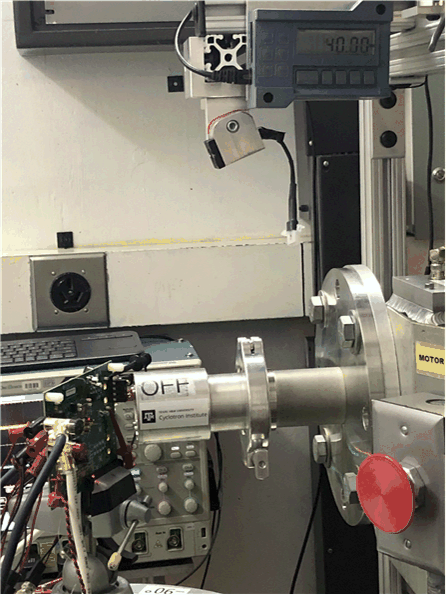
Figure 5-1 shows the TPS7H2201-SP test board used for the experiments at the TAMU facility. Although not visible in this photo, the beam port has a 1-mil Aramica window to allow in-air testing while maintaining the vacuum within the accelerator with only minor ion energy loss. Test points were soldered on the back for easy access of the signals while having enough room to change the angle of incidence and maintaining the 40 mm distance to the die. The air space between the device and the ion beam port window was maintained at 40 mm for all runs.
 Figure 5-1 Photograph of the TPS7H2201-SP
Mounted on the TPS7H2201EVM-CVAL in Front of the Heavy-ion Beam Exit Port at the
TAMU Accelerator Facility