SLVAE57B February 2021 – October 2021 LM5050-1 , LM5050-2 , LM5051 , LM66100 , LM74202-Q1 , LM74500-Q1 , LM74610-Q1 , LM74700-Q1 , LM74720-Q1 , LM74721-Q1 , LM74722-Q1 , LM7480-Q1 , LM7481-Q1 , LM76202-Q1 , SM74611 , TPS2410 , TPS2411 , TPS2412 , TPS2413 , TPS2419
- Trademarks
- 1 Introduction
- 2 Reverse Battery Protection
- 3 ORing Power Supplies
- 4 Reverse Battery Protection using MOSFETs
- 5 Reverse Polarity Protection vs Reverse Current Blocking
- 6 What is an Ideal Diode Controller?
- 7 Automotive Transient protection with Ideal Diode Controllers
- 8 ORing Power Supplies with Ideal Diode Controllers
- 9 Integrated Ideal Diode Solution
- 10Summary
- 11References
- 12Revision History
2.1 Reverse Battery Protection with Schottky Diode
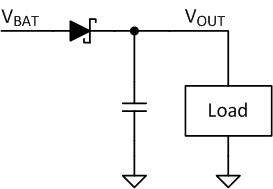
The simplest method of reverse battery protection is to add a series diode at input of the system power path. Figure 2-3 shows a reverse battery protection using a schottky diode. When the battery is installed correctly, load current flows in the forward direction of the diode. If the battery is installed with the wrong polarity, the diode is reverse biased and blocks reverse current, thereby protecting the load from negative voltage.
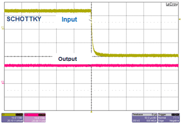
Figure 2-4 shows the response to a reverse polarity condition at the input. When the 12 V input is quickly reversed to -20 V, the output voltage remains without collapsing immediately or following the negative input as the schottky diode gets reverse biased and isolates the output from negative voltage. A bulk capacitor placed at the output holds the output from falling immediately and can supply the load for a short time before the input supply recovers.
 Figure 2-3 Reverse Battery Protection Using Schottky Diode
 Figure 2-4 Schottky Diode Response to Reverse Battery Condition
Drawbacks of using schottky diode for reverse battery protection include:
- Power dissipation: Forward conduction results in significant efficiency loss at higher load currents.
- Thermal management: Heat sink is needed to manage power dissipation, increasing cost and space.
- Reverse leakage current: Reverse leakage current of high voltage schottky diodes increase dramatically with junction temperature, resulting in higher power dissipation during reverse conduction.
- Head room for downstream power converter: During a cold start of the car, the battery voltage drops as low as 3 V or 4 V during a warm start. Forward voltage drop reduces subsequent power converter head-room and a wider operating power converter is required to work during 3 V or 4 V cold crank operation. This requires a wider VIN range DC/DC boost converter to be used after the diode.
On systems where large holdup capacitors are used, inrush current during startup can be huge and must not exceed the maximum diode current. This needs to be considered when choosing thermal layout or heat sink.