SLVUC04 December 2020 TLC6983
3 Test Setup
Table 3-1 shows the typical parameters for TLC6983 EVM.
Table 3-1 TLC6983EVM Parameters
| Parameter | Value |
|---|---|
| VCC Device supply voltage | 2.5-5.5 V |
| VLEDR/G/B supply voltage | 2.5-5.5 V |
| ICH Constant output source current | 0.2-20mA |
The TLC6983EVM can be setup and tested by following steps,
- USB Power supply
- Download the code to MSP430F5529 LaunchPadTM with TI CCS software.
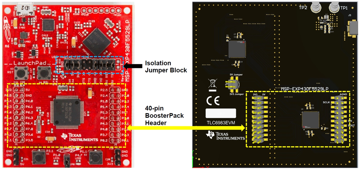
- Connect boosterpack connectors (J1, J2 on EVM board) with the MSP430F5529 LaunchPadTM, the connection method is shown as below figure.
- Disconnect J4 jumpers(5V/ 3V3) block and connect J3 with the mini-USB cable (the same cable with the MSP430F5529 LaunchPadTM ).
- External Power supply
- Download the code to MSP430F5529 LaunchPadTM with TI CCS software.
- Connect boosterpack connectors (J1, J2 on EVM board) with the MSP430F5529 LaunchPadTM, the connection method is shown in Figure 3-1.
- Disconnect J4 jumpers(5V/ 3V3) and connect TP1 and TP2 to 5V/GND power source.
- Power on 5V/GND power
supply.
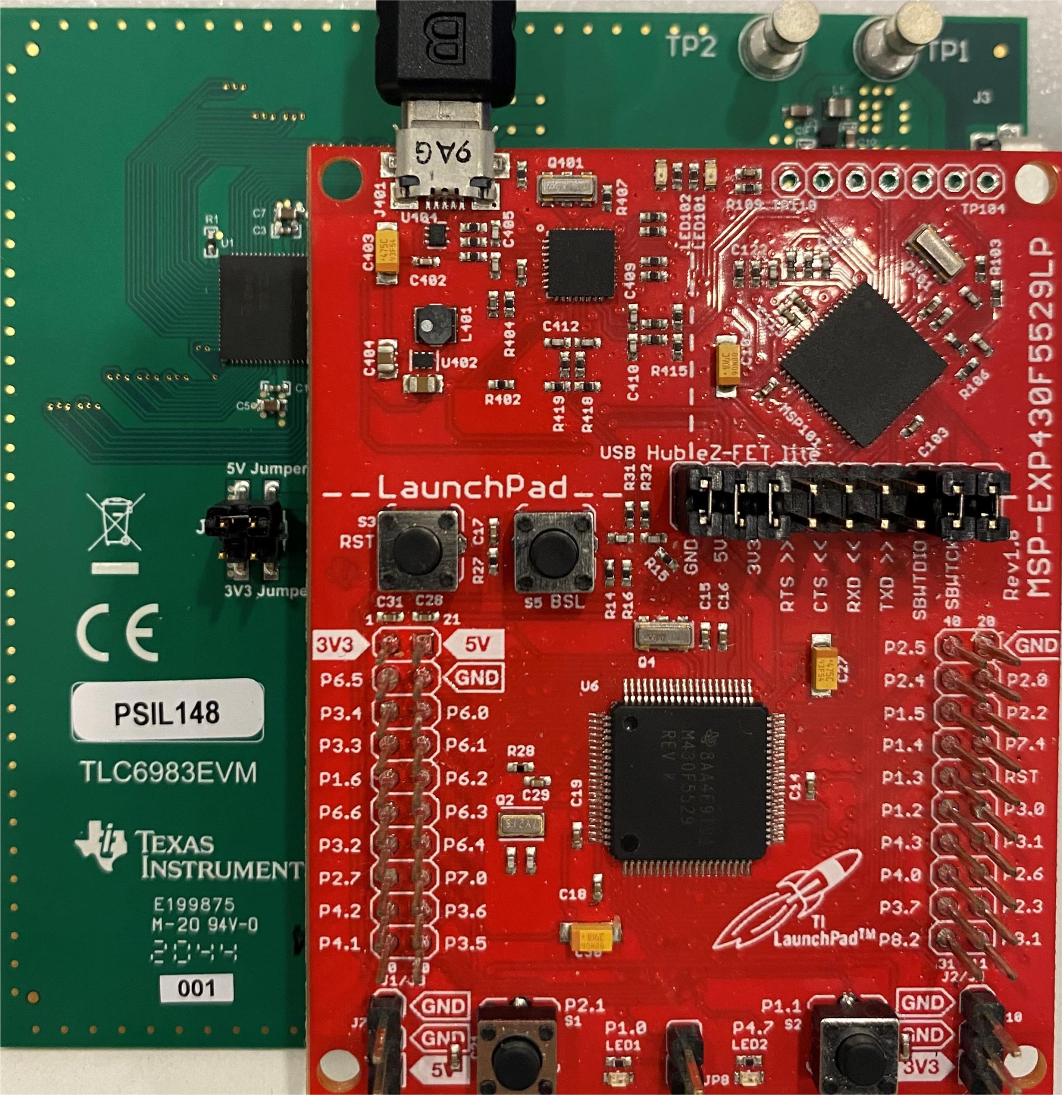
Figure 3-2 shows the hardware setup of the TLC6983 by using USB Power.

Figure 3-1 TLC6983EVM and MSP430F5529 LaunchPadTM connector pinout
Figure 3-2 TLC6983EVM hardware setup