SLVUCO1A May   2023  – April 2024 DRV8213 , DRV8214 , DRV8234

PRODUCTION DATA  

  1.   1
  2.   Description
  3.   Get Started
  4.   Features
  5.   Applications
  6.   6
  7. 1Evaluation Module Overview
    1. 1.1 Introduction
    2. 1.2 Kit Contents
    3. 1.3 Specification
    4. 1.4 Device Information
  8. 2Hardware
    1. 2.1 Headers and Test Points Information
    2. 2.2 Connector Information
    3. 2.3 Indicator LEDs
    4. 2.4 Hardware Setup
  9. 3Software
    1. 3.1 Software Setup
    2. 3.2 Web GUI Access or Local GUI Installation
    3. 3.3 Connecting EVM to GUI
    4. 3.4 GUI Overview
    5. 3.5 DRV8213EVM
    6. 3.6 DRV8214EVM, DRV8215EVM, DRV8234EVM, and DRV8235EVM
      1. 3.6.1 Quick Start
      2. 3.6.2 Dashboard
      3. 3.6.3 Register Map
    7. 3.7 Scripting Window
  10. 4Hardware Design Files
    1. 4.1 Schematics
    2. 4.2 PCB Layout
    3. 4.3 Bill of Materials (BOM)
  11. 5Additional Information
    1. 5.1 Trademarks
  12. 6Revision History

Headers and Test Points Information

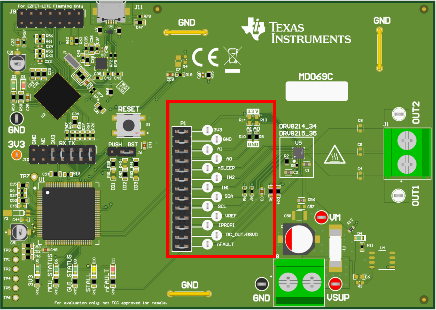
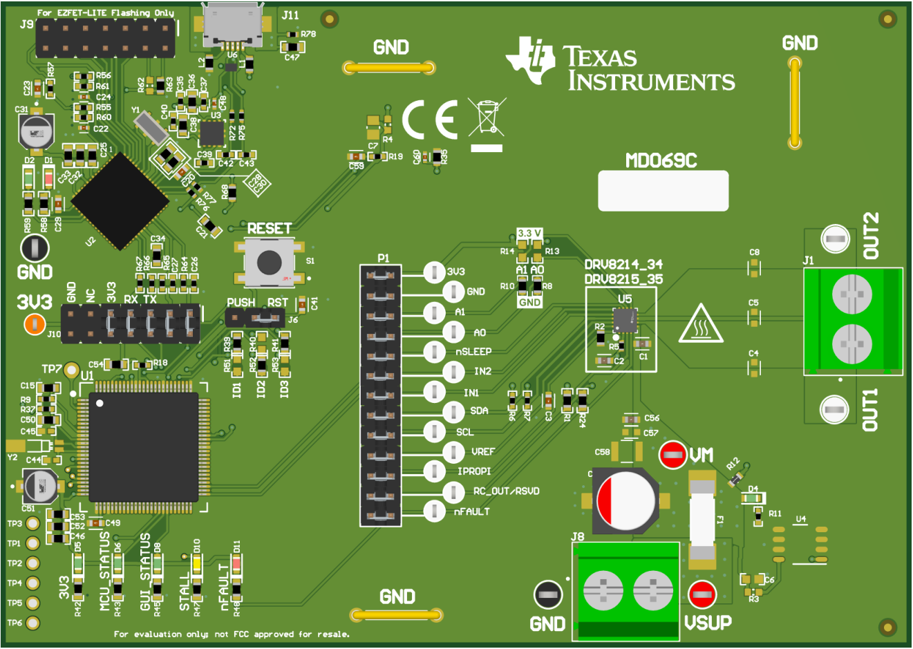
GUID-20240318-SS0I-58LV-BVCJ-ZCW5FZCRTXJ6-low.png Figure 2-1 DRV8214EVM (MD069-001) Top View
CAUTION: Hot surface temperature. The EVM can have high surface temperatures marked by the FIRE triangular symbol on the EVM. Avoid touching the marked hot surface area when driving high currents to prevent potential burn damage.
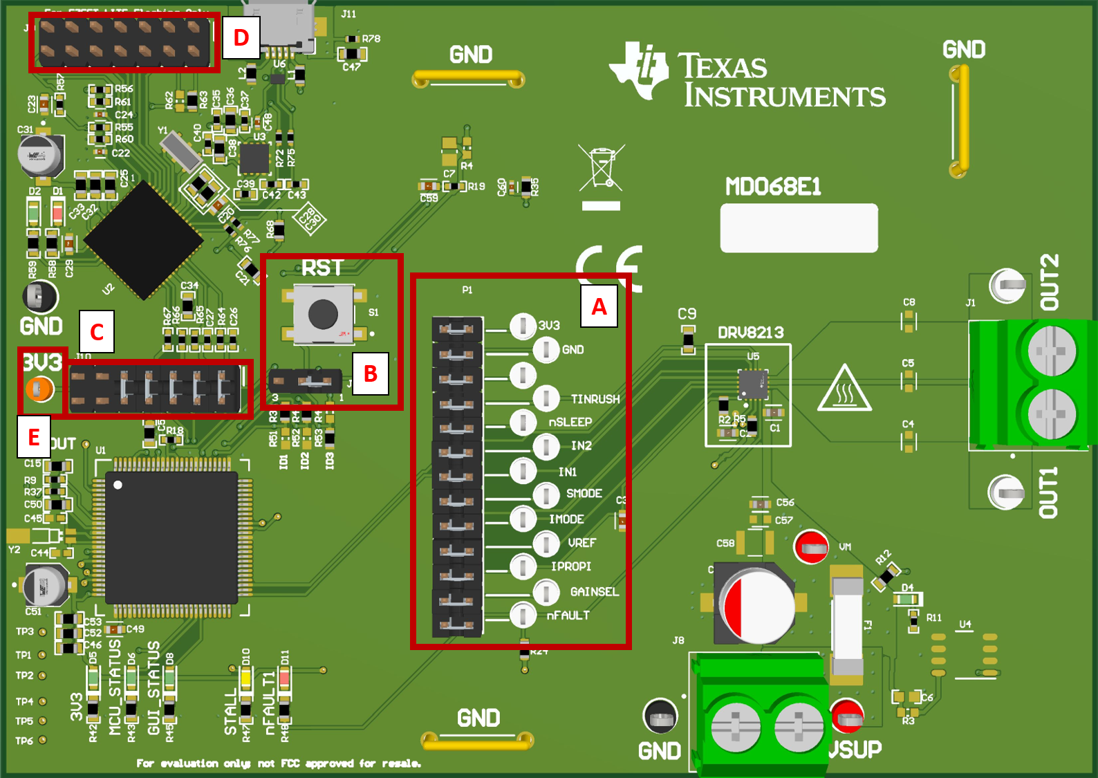
GUID-20230314-SS0I-TKBK-JL8P-JZW2XRVNPXLF-low.png Figure 2-2 DRV8213EVM Header and Test Point Information
Table 2-1 Header and Test Point Description - DRV8213EVM
Component labelDescription

A

Main signal header:

  • 3V3: 3.3V from LDO.
  • GND: GND test point.
  • TINRUSH: Sets timing for stall detection to ignore motor inrush current.
  • IN1: control input IN1.
  • IN2: control input IN2.
  • SMODE: stall detection response configuration (see Table 8-6. SMODE configuration of data sheet (SLVSGV9)).
  • IMODE: current regulation mode configuration (see Table 8-4. IMODE configuration of data sheet (SLVSGV9)).
  • VREF: current regulation reference voltage (tied to DAC of MSP430).
  • IPROPI: IPROPI pin voltage for monitoring voltage proportional output current.
  • GAINSEL: Configures IPROPI gain factor depending on the output current range (see Table 8-3. GAINSEL Setting of data sheet (SLVSGV9)).
  • nFAULT: fault indicator output (LOW = fault detected; HIGH= no fault detected).

B

Reset/PUSH button can have to functions based on the location of the SHUNT in J6 (below RST button):

  • RST (SHUNT in position 1): Pressing the button resets the MCU.
  • PUSH (SHUNT in position 3): Pressing the button does a user defined action. Currently not implemented in firmware.

C

JTAG connector between MSP430F5338 and MSP430F5528.

D

Connector for programming MSP430F5528 used in the eZ-FET lite debugger circuit. Only used one time by PCB manufacturer to programmed eZ-FET lite debugger MCU.

E

3V3 LDO connector.
GUID-20240318-SS0I-9SMG-JSZW-FCTFDFPGNKN8-low.png Figure 2-3 DRV8214, DRV8215, DRV8234, and DRV8235 EVM Header and Test Point Information
Table 2-2 DRV8214, DRV8215, DRV8234, and DRV8235 EVMs
Description

Main signal header:

  • 3V3: 3.3V from LDO.
  • GND: GND test point.
  • A0: Configures I2C device address along with A1 via R10 and R14 resistors (see Table 8-28. Device Addresses of data sheet).
  • A1: Configures I2C device address along with A0 via R8 and R13 resistors (see Table 8-28. Device Addresses of data sheet).
  • nSLEEP: device nSLEEP pin (LOW = ASLEEP & HIGH = AWAKE).
  • IN2: control input IN2.
  • IN1: control input IN1.
  • SDA: Data line of I2C bus.
  • SCL: Clock line of I2C bus.
  • VREF: current regulation reference voltage (tied to DAC of MSP430).
  • IPROPI: IPROPI pin voltage for monitoring voltage proportional output current.
  • RC_OUT (not applicable to DRV8215EVM or DRV8235EVM): Ripple count pulse output from the driver. Corresponds to the ripples of the motor during commutation.
  • nFAULT: fault indicator output (LOW = fault detected; HIGH= no fault detected).