SLYA061 August 2022 DRV5011 , DRV5013 , DRV5013-Q1 , DRV5015 , DRV5015-Q1 , TMAG5110 , TMAG5110-Q1 , TMAG5111 , TMAG5111-Q1
1 Application Brief
Introduction
Motors convert electrical energy into mechanical energy, enabling motion control of components connected to them. This is typically done by controlling the rotation of the motor’s shaft and connecting external components to the shaft so that they rotate along with it. Causing the external component to move is not enough for many systems—they must also monitor the speed of the external component so that it could be refined to meet system requirements. Figure 1-1 shows an example of a two-wheel system with two individual motors, each one connected to a different wheel to control each wheel separately. A gearbox is commonly used in these applications to deliver more torque from the motor at lower speeds. This gearing results in multiple shaft revolutions per each wheel rotation.
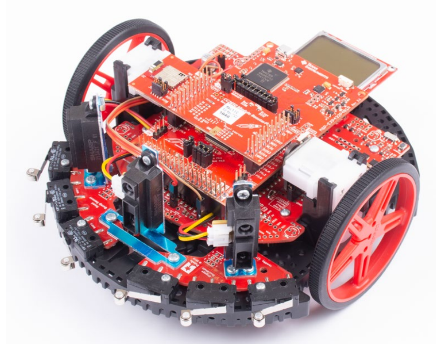 Figure 1-1 Two-Wheel Robot.
 A difference in speed may occur between the wheels due to the mechanical and electrical variations for different motors in the system, even if the same signal is used to control the speed of both the motor wheels. This may cause a problem if the user wants the robot to move in a straight line, because a slight difference in speed may cause the robot to gradually move slightly to the left or slightly to the right from the intended path. To overcome this, a separate signal for controlling the speed of each motor may be used as well as a mechanism to measure the speed at which each motor shaft is rotating. Based on the speed measurement of the different motor shafts, the speed control signals of the two motors can be feed back to the system and adjusted so that the speed of the wheels is approximately the same, thereby allowing the robot to move in a straight line as desired.
To detect the speed of each motor shaft, either an incremental or absolute encoder may be used. An absolute encoder can provide information on the position of the shaft itself. An incremental encoder, on the other hand, simply provides information on the incremental change in position instead of the exact position of the shaft, which is sufficient for measuring the shaft speed. Magnetic incremental encoders and optical incremental encoders are two common implementations for incremental encoding.
Optical Incremental Encoding
Optical incremental encoding uses an emitter, code disc, and optical sensor to measure the speed of the motor shaft connected to the code disc. The emitter, which can be an infrared LED, creates a light beam that is sensed by the optical sensor, typically a photodiode or phototransistor. The code disc is placed between the emitter and the optical sensor and, as the motor shaft rotates, the code disc will rotate along with the motors shaft. The code disc is designed so that it alternates between allowing and blocking the light beam’s propagation to the optical sensor as the code wheel turns. The output of the optical sensor circuit is a logic signal that has its state set based on whether the light beam passes to the optical sensor or if it is blocked from being received by the optical sensor.
One implementation of a code disc uses alternating transparent and opaque regions. When a transparent portion of the code disc is between the emitter and optical sensor, the optical sensor circuit detects this and asserts its output accordingly. On the other hand, when an opaque portion of the code disc is between the emitter and optical sensor, the light beam is blocked from being received by the optical sensor, which results in the optical sensor circuit’s output being asserted to the opposite logic state than when the transparent portion of the code disc is between the emitter and optical sensor.
An alternative optical incremental encoding uses slits that are placed on the code wheel, which allows the light beam to propagate to the optical sensor. Figure 1-2 shows an example where a slit is between the emitter and optical sensor, which allows the light beam to propagate to the optical sensor.
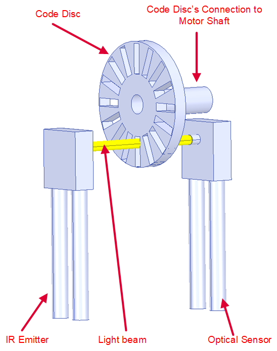 Figure 1-2 Light Beam Propagating Through
Slit to Optical Receiver.
 Figure 1-3 shows the light beam blocked from the optical sensor when the non-slit region of the code wheel is between the emitter and optical sensor.
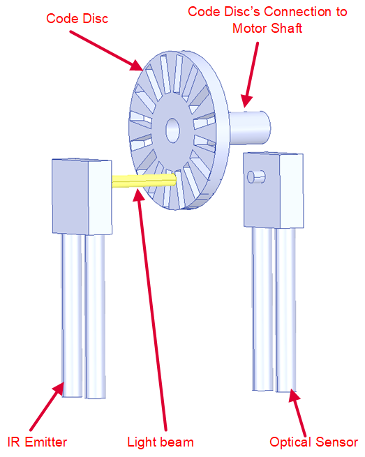 Figure 1-3 Light Beam Blocked by Non-Slit
Region of Code Disc.
 Use Equation 1 to calculate the electrical frequency in which the output of the optical sensor changes:
Where:
- Transitions is the change in transition count during the “ time interval.
This equation assumes that both rising and falling edges increment the transition count.
Use Equation 2 to calculate the frequency in which the shaft rotates:
Where:
- Slits is the total number of slits on the code wheel for a slit/non-slit code disc implementation (or the total number of transparent regions for transparent/opaque code disc implementations).
A gearbox may be used to optimize the torque in the motor for optimal performance when driving the external component. An example external component driven by a motor that may have a gearbox is a wheel. In this case, the gearbox may be used to optimize the torque in the motor for optimal performance, battery life, and traction of the wheel.
If a gearbox is used to drive the external object, use Equation 3 to calculate the frequency of the object:
Where:
- Gear_ratio is the gear ratio between the motor and the object.
Magnetic Incremental Encoding
Magnetic incremental encoding is implemented by placing a magnetic disc on the motor shaft so that it rotates along with the motor’s shaft. Figure 1-4 shows an example for magnetic incremental encoding that uses a 1D Hall latch. The magnetic disc mounted on the motor is typically composed of multiple sets of north/south poles.
 Figure 1-4 Incremental Wheel Encoding With a Single 1D Hall Latch.
 The Hall latch detects changes in the magnetic field polarity and will either toggle the output high or low when the magnetic field meets the BOP or BRP sensitivity specification. The Hall latch changes its output every time it senses a transition between a south pole to a north pole or a north pole to a south pole (Figure 1-5 exhibits the output behavior of a Hall latch).
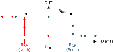 Figure 1-5 Hall Latch Output State.
 Use Equation 4 to calculate the electrical frequency in which the output of the magnetic sensor changes:
The number of transitions per magnetic disc revolution observed on the output of the Hall latch will equal the number of poles on the magnetic disc. As an example, a six-pole magnet will have six total transitions (three rising edges and three falling edges). Consequently, use Equation 5 to calculate the frequency of the shaft:
Where:
- Poles is the total number of poles of the magnet, which includes the sum of both the number of north and south poles of the magnet.
Increasing the number of poles on a magnetic disc increases the position sensing resolution. This also decreases the generated magnetic flux density, however, until it is eventually too small to affect the output of the Hall latch. Designers should perform magnetic simulations on the number of poles, magnet size, magnetic material, and air gap to verify that the desired disc produces a magnetic flux density that is beyond the BOP and BRP range of the selected latch so that the output of the Hall latch can change accordingly as the disc rotates. High sensitivity latches have small BOP and BRP, which allows designers to use smaller magnets or allow larger air gaps between the magnet and sensor.
Use Equation 6 to calculate the frequency of the object driven by the motor:
To measure the speed of the motor, only one 1D latch is needed. To determine both the speed and direction of the motor (whether the motor moves clockwise or counterclockwise), however, a second 1D latch is needed, and Figure 1-6 shows that the second 1D latch must be offset by 90 electrical degrees. This is accomplished by placing the two Hall-effect latches separated by any interval of n +1/2 poles. Figure 1-6 shows how to use one 2D latch as an alternative to using two 1D latches in an application. The 2D latch has two internal 1D latches that are already 90 degrees offset from each other, which give designers more flexible device placement. Using two 1D latches or one 2D latch can also increase the resolution compared to using one 1D latch because the position information is present on two outputs instead of only one.
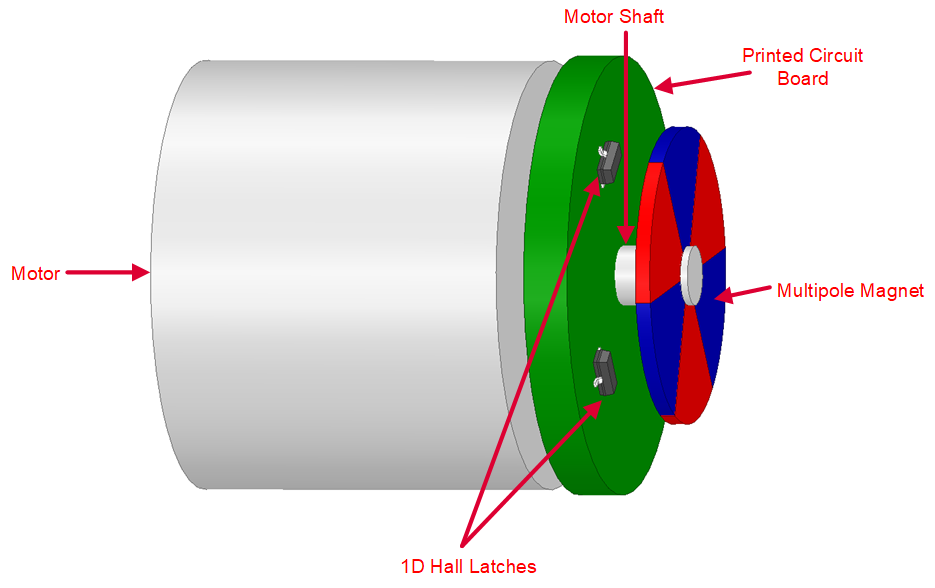 Figure 1-6 Incremental Wheel Encoding With Two 1D Latches
for Determining Speed and Direction.
 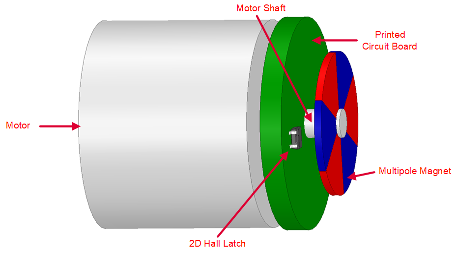 Figure 1-7 Incremental Wheel Encoding With a Single 2D
Latch for Determining Speed and Direction.
 Selecting Between Magnetic or Optical Incremental Encoding Solutions
The primary advantages of optical encoders are their increased resolution and accuracy compared to magnetic encoders. Although optical encoders have relatively high accuracy and resolution, these types of encoders have multiple disadvantages that make magnetic encoders better suited for many applications.
Optical encoder disadvantages include the following:
High Current consumption: In some cases, the emitter requires a relatively high current to generate the light beam sensed by the optical sensor. For battery-operated systems, the high current consumption of an emitter would reduce the lifetime of the battery.
Reduced lifetime: Code discs, which are often constructed with glass or plastic, are susceptible to damage. As a result, they are not ideal for systems where collisions with other objects can occur or in systems constantly exposed to vibrations. The emitters themselves also are prone to failures, which further reduces the lifetime of optical encoders.
Larger Size: Sealing an optical encoder to make it less susceptible to external influences can result in a relatively bulky and more expensive solution compared to magnetic encoders, which do not require being sealed for robustness against many external influences.
Susceptibility to External Particles: If the code disc is exposed to external particles, such as dirt, dust, oil, moisture, or other debris, the operation of the optical encoder may also be affected if the propagation of the light beam from the emitter to the optical sensor is blocked due to these external particles. The code disc may be exposed to the external particles during the installation of the code wheel onto the motor shaft or also during the normal operation of the encoder. To deal with the susceptibility of optical encoders to external particles, the encoder may be sealed; however, sealing the encoder may not fully prevent external particles from entering the seal and affecting the encoder. In addition, sealing the encoder results in a larger size that may not be ideal for many applications. In Figure 1-8 below, dirt is present in a few of the slits in the disc wheel. Consequently, even if the slit is directly between the emitter and optical sensor in Figure 1-7, the light beam of the emitter does not always propagate to the optical sensor as expected. The external particles, therefore, impacts the optical encoder’s measurement of the shaft and object frequency.
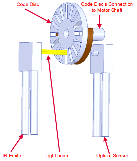 Figure 1-8 Light Beam Blocked by
Dirt.
 The disadvantages of optical encoders are why magnetic encoders are better suited for systems that are deployed in dirty, harsh environments, such as the environments common in industrial applications.
Recommended Devices
Hall latches are selected based on the following requirements: sensitivity, frequency bandwidth, current consumption, jitter, output delay, size, sensing direction, operating voltage range, output type (open-drain versus push-pull output), and temperature range. For more information on how these specifications impact system performance, watch the Specifications of Hall-effect latches for rotary encoding video.
Texas Instruments has multiple Hall latches. Table 1-1 lists the different features of these latches.
| DEVICE | CHARACTERISTICS |
|---|---|
| TMAG5110 | 2D Hall-effect latch with independent 2D outputs |
| TMAG5111 | 2D Hall-effect latch with speed and direction outputs |
| DRV5011 | 1D, Low voltage, small size 1D Hall-effect latch |
| DRV5013 | 1D, High voltage Hall-effect 1D latch |
| DRV5015 | 1D, High sensitivity, low voltage 1D Hall-effect latch |