SLYT830 June 2022
4 Design implementation and test results
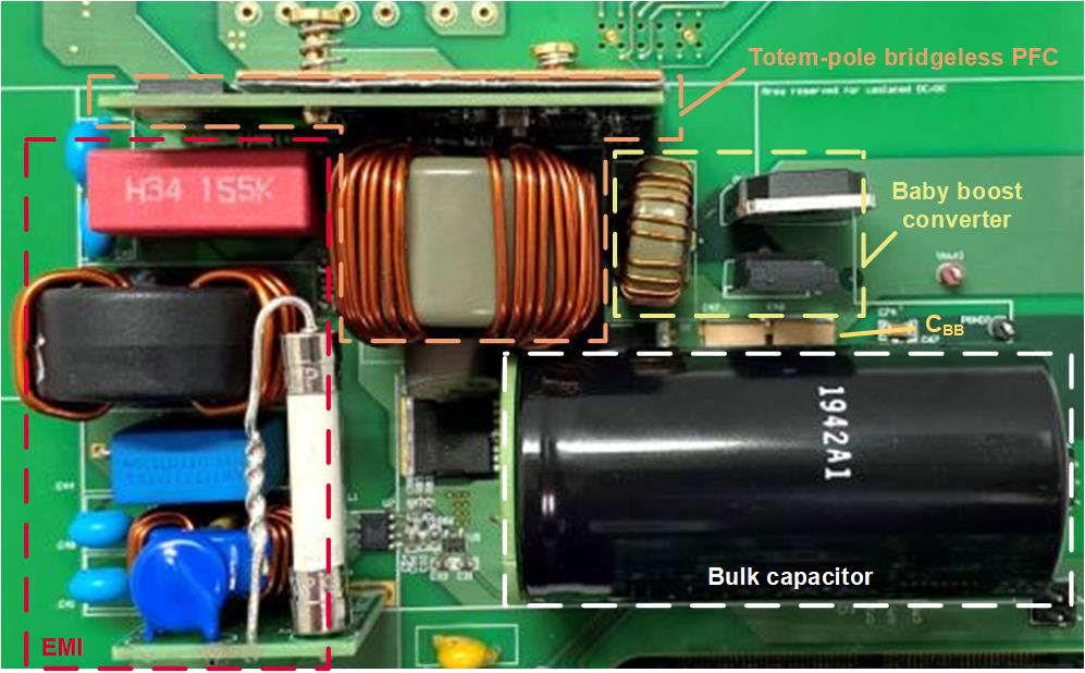
Figure 4-1 shows the Texas Instruments (TI) 3.6-kW Single-Phase Totem-Pole Bridgeless PFC Reference Design with >180-W/in3 Power Density, which uses a baby boost converter [6]. TI’s LMG3522R030 GaN device, which has zero reverse-recovery charges, minimizes switching losses in the totem-pole bridgeless PFC. All of the components are placed in an x and y dimension less than 68 mm by 121 mm, with a maximum component height of 32 mm. The reference design achieves >180-W/in3 power density and 98.7% peak efficiency. The selected CBULK is a 910-μF 450-V aluminum capacitor.
Although the required capacitance is only 635 μF, the ripple current rating on available capacitors with less than 910 μF of capacitance is not enough to handle the ripple current generated by a single-phase 3-kW PFC. Two 1-µF 450-V ceramic capacitors serve as CBB, which are nicely utilized in the space under the bulk capacitor.
The design applies a Magnetics 0076381A7 core to the baby boost inductor, with 23 turns on the inductor. The inductance at 0 A and 25 A is 22.75 μH and 9.1 μH, respectively. The 9.1-μH inductance allows peak current less than the 25-A target.
 Figure 4-1 3.6-kW single-phase totem-pole
bridgeless PFC reference design with >180-W/in3 power density.
Figure 4-1 3.6-kW single-phase totem-pole
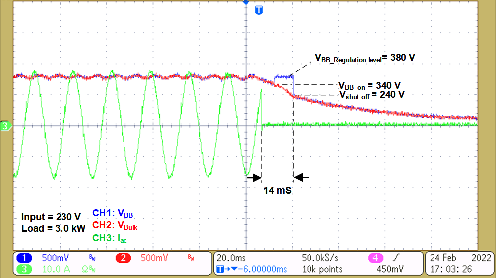
bridgeless PFC reference design with >180-W/in3 power density.Figure 4-2 shows the measurement of an AC dropout event on the 3-kW PFC reference design. When the AC voltage drops down to 0 V (as does the AC current), CBULK and CBB continuously deliver the energy stored to the load. Once VBulk drops down to 340 V, the bypass FET turns off and the baby boost converter starts to operate, boosting VBB to 380 V. The baby boost converter continuously operates until VBulk drops down to 240 V. VBB remains above the targeted isolated DC/DC minimum operational input voltage of 320 V for 14 mS.
 Figure 4-2 Waveforms at an AC dropout
event.