SLYY200A April 2021 – December 2023 LM25149 , LM25149-Q1 , LM5156-Q1 , LM5157-Q1 , LM53635-Q1 , LM60440-Q1 , LM61460-Q1 , LM61495-Q1 , LMQ62440-Q1 , LMR33630-Q1 , LMS3655-Q1 , TPS55165-Q1 , UCC12040 , UCC12050
- 1
- Overview
- At a glance
- What is EMI?
- Conventional methods to reduce EMI in the low- and high-frequency ranges
- Innovations in reducing low-frequency emissions
- Spread spectrum
- Active EMI filtering
- Cancellation windings
- Innovations in reducing high-frequency emissions
- HotRod™ package
- Enhanced HotRod QFN
- Integrated input bypass capacitor
- True slew-rate control
- EMI modeling capabilities
- Low-frequency EMI designs using WEBENCH® design tool
- Conducted and radiated EMI results published in data sheets
- Conclusion
- Keep product categories for low EMI
Integrated input bypass capacitor
As we described earlier, a large input power loop results in higher emissions at high-frequency bands because of increased switch-node ringing. Integrating high-frequency input decoupling capacitors inside the device package helps minimize the input loop parasitic and thus reduces EMI. This technique is used in the LMQ62440-Q1, a step-down converter, as shown in Figure 20 on the following page. Beyond reducing the input power-loop inductance, the package integration of the input high-frequency capacitors also helps make the solution more immune to changes in the board layout of the end system.
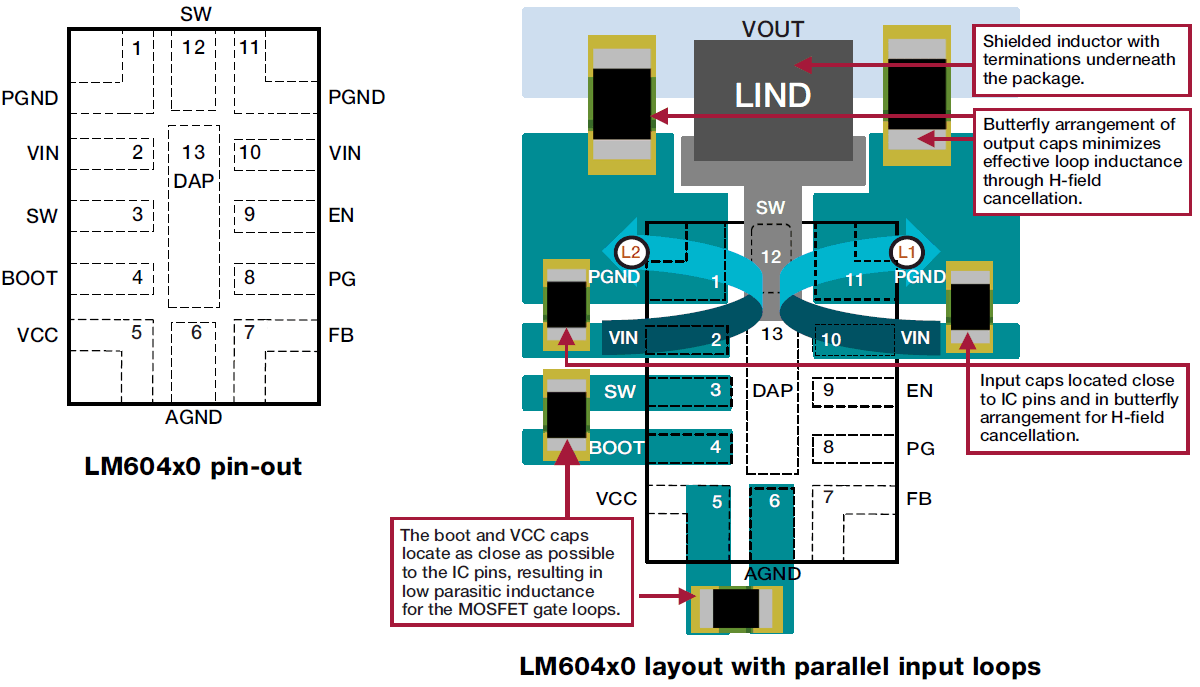
 Figure 19 The pinout and PCB layout on
an Enhanced HotRod QFN package device.
Figure 19 The pinout and PCB layout on
an Enhanced HotRod QFN package device.bands because of increased switch-node ringing. Integrating high-frequency input decoupling capacitors inside the device package helps minimize the input loop parasitic and thus reduces EMI. This technique is used in the LMQ62440-Q1, a step-down converter, as shown in Figure 21. Beyond reducing the input power-loop inductance, the package integration of the input high-frequency capacitors also helps make the solution more immune to changes in the board layout of the end system.
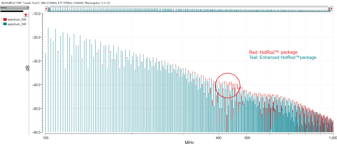
 Figure 20 SW node FFT comparison of
HotRod- vs. Enhanced HotRod-packaged device.
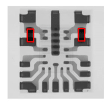
 Figure 21 Two high-frequency input
bypass capacitors integrated in the LMQ62440-Q1 device.
Figure 21 Two high-frequency input
bypass capacitors integrated in the LMQ62440-Q1 device.Figure 22 compares the radiated EMI — identical conditions on identical boards — of the LMQ62440-Q1, with and without the bypass capacitors integrated. The results show a 9-dB reduction in emission in the most stringent TV band (200 to 230 MHz), which helps the system remain under EMI limits set by industry standards without the need for additional components on the board.