SNLA423 March 2023 DP83826E
- 1Trademarks
- 2DP83826 Application Overview
- 3Troubleshooting the Application
- 4Conclusion
- 5Revision History
2 DP83826 Application Overview
The DP83826 offers low and deterministic latency, low power, and supports 10BASE-Te, 100BASE-TX Ethernet protocols to meet stringent requirements in real-time industrial Ethernet systems. The device includes hardware bootstraps to achieve fast link-up time, fast link-drop detection modes, and dedicated reference CLKOUT to clock synchronize other modules on the systems.
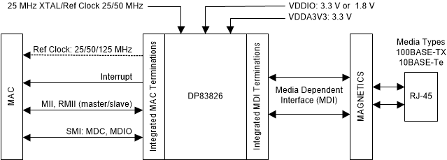
Figure 2-1 is a high-level system block diagram of a typical DP83826 application.
 Figure 2-1 DP83826
Block Diagram
Figure 2-1 DP83826
Block DiagramThe DP83826 connects to an Ethernet MAC and to a media. The connection to the media is via a transformer and a connector.
TI is transitioning to use more inclusive terminology. Some language may be different than what you would expect to see for certain technology areas.